Ultra-high efficiency ballast with end of lamp life protection

a technology of end-of-lamp life protection and ultra-high efficiency, which is applied in the direction of electric variable regulation, process and machine control, instruments, etc., can solve the problems of reducing the efficiency of discharge and lamp, one or more electrode filaments may fail and be open, and the self-oscillating circuit commonly used in electronic ballasts often perform undetectedly. , to achieve the effect of increasing efficiency

Active Publication Date: 2013-07-16
TECHN CONSUMER PRODS
View PDF2 Cites 13 Cited by
  • Summary
  • Abstract
  • Description
  • Claims
  • Application Information

AI Technical Summary

Benefits of technology

[0030]Observing the shortcomings of the prior art discussed above, it is an object of this invention to provide, in one embodiment, a self-oscillating electronic ballast for discharge tube type lamps which increases efficiency and has IEC-standard end of lamp life protection.
[0031]In embodiments, the present invention enhances efficiency in a variety of ways. Placing a primary resonant capacitor in parallel with the cathode conduction loop while retaining a minimal secondary resonant capacitor within the cathode conduction loop significantly reduces the amount of power dissipated as heat through the cathode filaments. This can save 80% or more of the energy otherwise lost to such dissipation. Additionally, driving the bases of the transistors in the self-oscillating circuit with a high-impedance, low saturation transformer allows the operating frequency of the self-oscillating circuit to approach the resonant frequency of the load. Efficiency of the ballast increases significantly as these frequencies near each other, leading to an efficiency improvement of as much as 10%.
[0032]End of lamp life protection compliant with internationally recognized standards is also achieved by embodiments of the present invention. The primary winding of the base drive transformer is placed within the cathode conduction loop of the ballast circuit, and a decoupling capacitor damps the erroneous base drive signals generated by coupling in the secondary windings as a lamp nears end of lamp life. This arrangement invariably forces the ballast circuit to cease oscillation when a cathode filament opens or presents unduly high impedance. Additionally, balancing diodes protect the oscillating transistors from damage due to reverse bias in current which may occur as a lamp approaches end of lamp life.

Problems solved by technology

However, the self oscillating circuits commonly used in electronic ballasts often perform undesirably as the lamp approaches the end of lamp life.
Where the first and second electrodes of the discharge tube take the form of a filament between two conductive pins, one or more electrode filament may fail and be open as the lamp approaches end of lamp life.
This situation significantly reduces the efficiency of the discharge and lamp and causes the electrodes to overheat.
This heat is conducted through to the exterior of the tube, causing the plastic to discolor, melt, and even burn, which is undesirable.
Even when the electrode ends of the discharge tube are not in contact with a plastic housing, it is nevertheless undesirable to have superheated lamp tube surfaces.
This arrangement, while improved, still exhibits undesirable characteristics because all current must flow through the cathode conduction loop.
First, the circuit is inefficient.
Directing all power through the electrodes causes significant power dissipation without producing light, and limiting the efficiency of the circuit's light output to around 85%.
Additionally the increased thermal wear on the filament reduces lamp life.
Second, the end of lamp life protection on this circuit is limited.
This is undesirable as power is dissipated as heat at a rate much higher even than under normal operating conditions.
The heat may reach potentially dangerous levels, and the efficiency of the lamp and ballast circuit is drastically reduced.
Additionally, the ballast may cease to oscillate consistently, causing reduced light output or visually disturbing flickering and pulsing.
These end of lamp life modes do not meet recognized end of lamp life protection standards.

Method used


Image

  • Ultra-high efficiency ballast with end of lamp life protection
  • Ultra-high efficiency ballast with end of lamp life protection
  • Ultra-high efficiency ballast with end of lamp life protection

Examples


Embodiment Construction

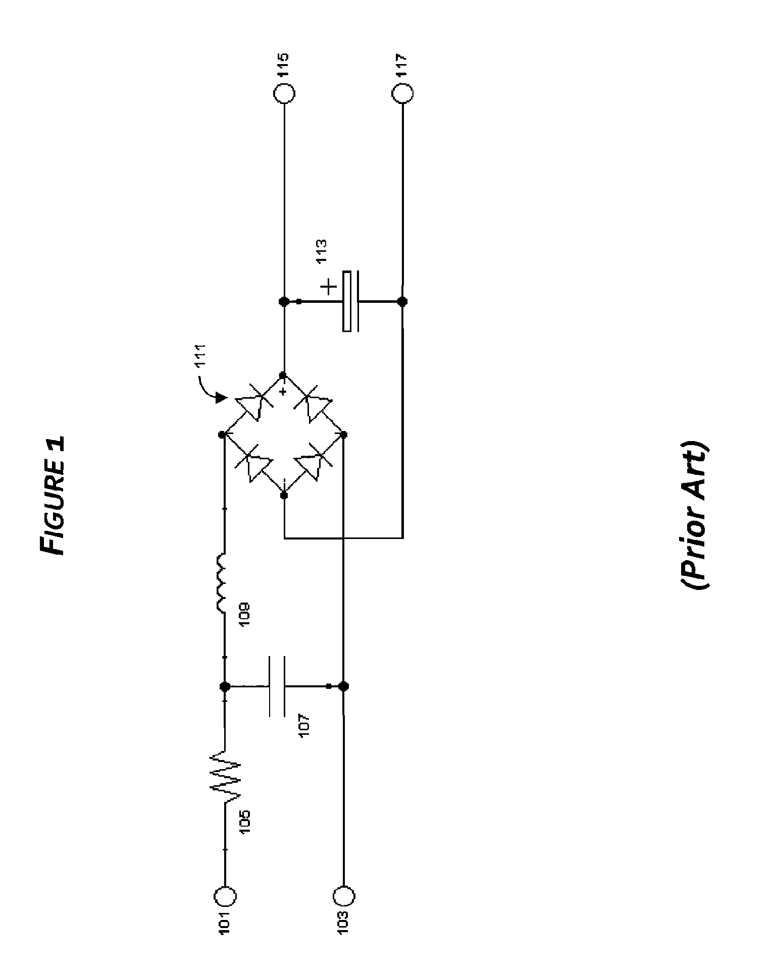
[0038]The present invention provides an increase in the efficiency of self-oscillating resonant ballast and lamp circuits over the normal operating life of the lamp. Additionally it provides a cost effective end of lamp life solution for a self-oscillating resonant electronic ballast, offering protection against overheating and meeting IEC end of lamp life protection standards. Referring now to FIG. 1, an exemplary AC to DC rectification and smoothing circuit suitable for use with embodiments of the invention is described. AC current is supplied to the circuit on hot wire 101 and neutral wire 103. Hot wire 101 is connected in series through fusible resistor 105 to EMI suppression capacitor 107 and EMI Suppression Inductor 109. Capacitor 107 is connected back to neutral 103. Inductor 109 is connected through to an AC terminal of diode bridge rectifier 111. The second AC terminal of rectifier is connected back to capacitor 107 and to neutral 103. The positive terminal of rectifier 111...


PUM


Abstract

In one embodiment, a self-oscillating electronic ballast for discharge tube type lamps which increases efficiency and has IEC-standard end of lamp life protection. Efficiency is enhanced by placing primary resonant capacitor (351a) in parallel with cathode conduction loop (270) while retaining a minimal secondary resonant capacitor (351b) within the cathode conduction loop (270). IEC-standard end of lamp life protection is achieved by placing the primary winding (323) of the base drive transformer (357) within the cathode conduction loop (270) of the ballast circuit, and employing a dampening capacitor (307) to suppress the erroneous base drive signals generated by coupling in the secondary windings (325, 327) as a lamp nears end of lamp life. Other embodiments are described and shown.

Description

CROSS REFERENCE TO RELATED APPLICATIONS[0001]This application claims the benefit of provisional patent application Ser. No. 61 / 215,191, filed May 1, 2010 by the present inventors, TIMOTHY CHEN AND JAMES KEVIN SKULLY, which is incorporated herein by reference.FIELD OF THE INVENTION[0002]The present application relates generally to a ballast circuit for fluorescent lamps. Specifically, this application relates to a self-oscillating ultra-high efficiency electronic ballast circuit incorporating cost-effective protection for open-cathode and other end of lamp life failure modes.BACKGROUND OF THE INVENTION[0003]Fluorescent lighting systems of various types are commonly employed in a myriad of lighting applications. All fluorescent lighting systems are gas-discharge lamp systems and generate light by sending an electrical discharge through an ionized gas. The gas in any such system must be isolated from the surrounding atmosphere and electrically driven to a sufficient and sustained state...

Claims


Application Information

Patent Timeline
Patent Type & Authority Patents(United States)
IPC IPC(8): H05B37/02
CPCH05B41/2855Y02B20/185Y02B20/00
Inventor CHEN, TIMOTHYSKULLY, JAMES KEVIN
Owner TECHN CONSUMER PRODS
Why Eureka
Try Eureka