Method for manufacturing FRP member with insert and FRP member with insert

a technology of fiber reinforced plastics and manufacturing methods, applied in manufacturing tools, threaded fasteners, ways, etc., can solve problems such as adhesive deterioration, and achieve the effects of reducing manufacturing costs, improving productivity, and reducing the time required for dry machining

Active Publication Date: 2013-07-23
TOYOTA JIDOSHA KK
View PDF32 Cites 4 Cited by
  • Summary
  • Abstract
  • Description
  • Claims
  • Application Information

AI Technical Summary

Problems solved by technology

Also, at the time of bonding the FRP members together by an adhesive, for example, adhesion therebetween may be inhibited by the oil attaching thereto, to thereby deteriorate adhesiveness.

Method used


Image

  • Method for manufacturing FRP member with insert and FRP member with insert
  • Method for manufacturing FRP member with insert and FRP member with insert
  • Method for manufacturing FRP member with insert and FRP member with insert

Examples


Embodiment Construction

[0031]Next, embodiments according to the present invention will be described with reference to the drawings.

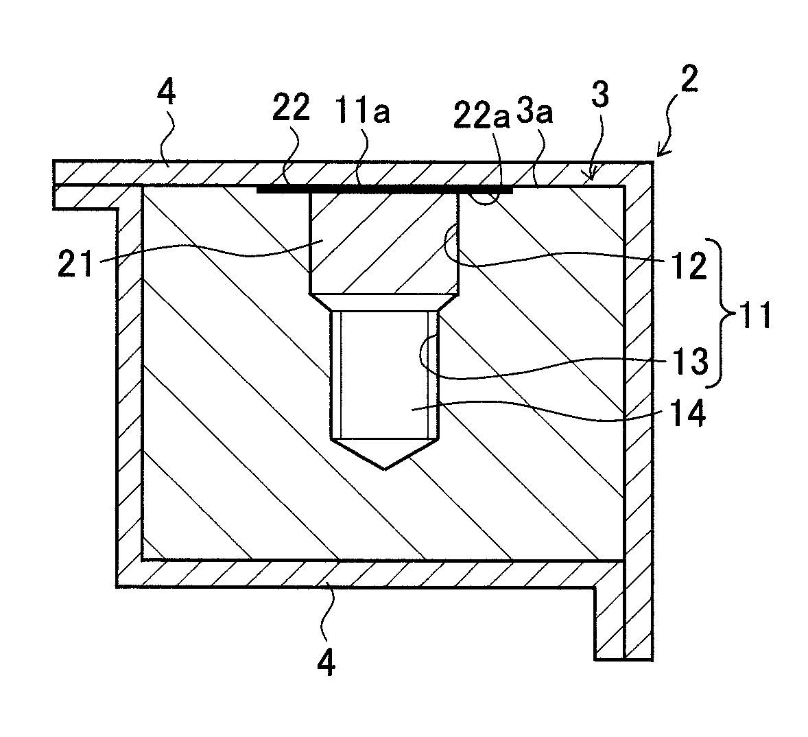
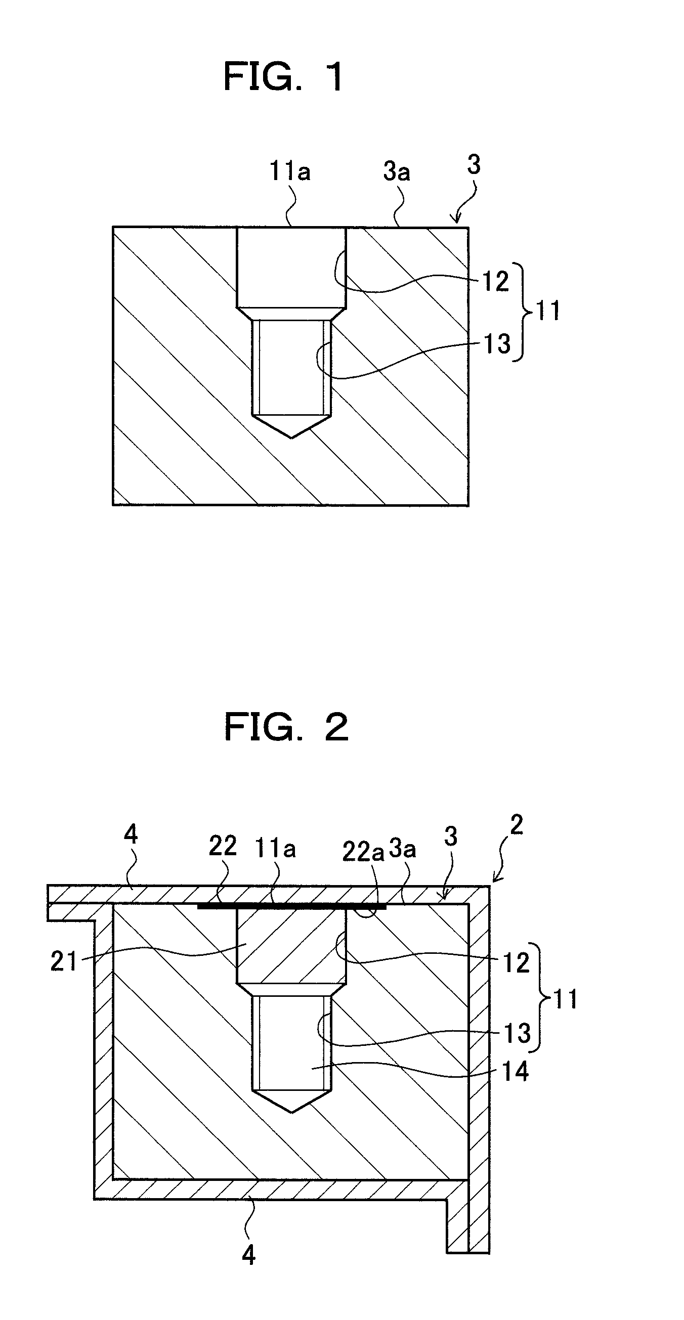
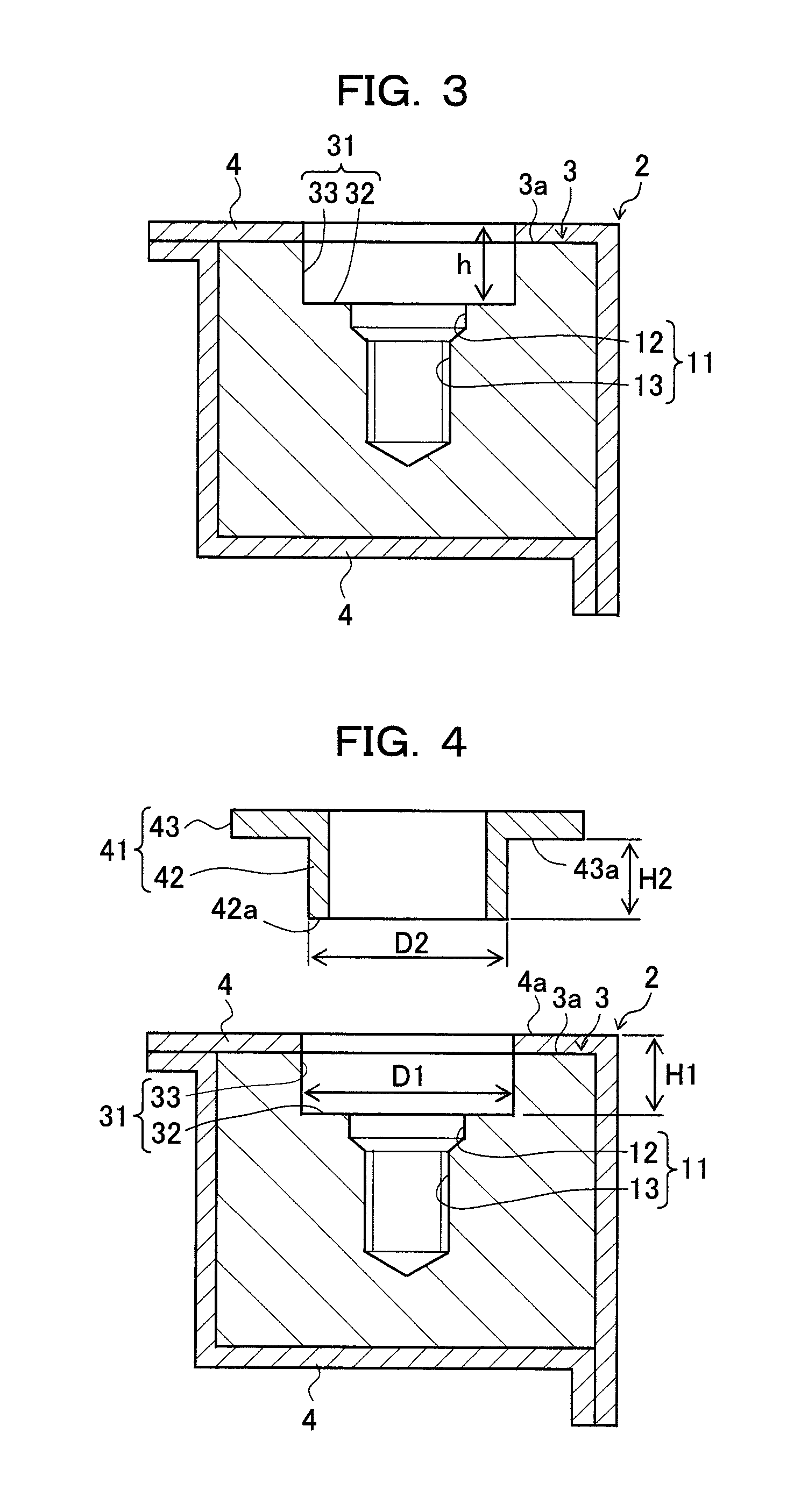
[0032]FIG. 1 is a sectional view of an insert 3 for explaining an insert machining step. FIG. 2 is a sectional view of an FRP member 2 for explaining an FRP molding step. FIG. 3 is a sectional view of the FRP member 2 for explaining a boring step. FIG. 4 is a sectional view of the FRP member 2 for explaining a collar mounting step. FIG. 5 is a sectional view illustrating a finished state of an FRP member 1 with insert. FIG. 6 is a sectional view illustrating an example in which the FRP member 1 with insert is in a fastened state. Although the upper side and the lower side in the drawings are respectively referred to as an upper side and a lower side for the convenience of description, the upper side and the lower side do not necessarily correspond to those relative to the ground.

[0033]In a present embodiment, the FRP member 1 with insert can be obtained through the four machin...


PUM

PropertyMeasurementUnit
strengthaaaaaaaaaa
adhesionaaaaaaaaaa
adhesivenessaaaaaaaaaa

Abstract

Provided is a method for manufacturing an FRP member with insert which enables to reduce a machining time to improve productivity. First, a threaded hole 11 is formed in an insert 3. An FRP member 2 where at least the threaded hole 11 of the insert 3 is covered with a coating 4 made of FRP is molded. A counter-bored hole 31 that penetrates the coating 4 of the FRP member 2 to communicate with the threaded hole 11 of the insert 3 is formed, to thereby obtain an FRP component 1 with insert. Accordingly, a machining step after molding the FRP member 2 in which dry machining is required includes only the boring step of forming the counter-bored hole 31 in the FRP member 2. Thus, the machining time can be reduced, and the productivity can be improved.

Description

CROSS REFERENCE TO RELATED APPLICATIONS[0001]This application is a National Stage of International Application No. PCT / JP2009 / 059606 filed May 26, 2009, claiming priority based on Japanese Patent Application No. 2008-141299, filed May 29, 2008, the contents of all of which are incorporated herein by reference in their entirety.TECHNICAL FIELD[0002]The present invention relates to a method for manufacturing an FRP (Fiber Reinforced Plastics) member that encompasses an insert, and an FRP member with insert.BACKGROUND ART[0003]A conventional method of mounting a mounting component on an FRP member includes a method of embedding a metal insert in the FRP member, and fastening the mounting component by use of a threaded hole of the insert.[0004]For example, as shown in FIG. 8, Patent Document 1 discloses a technique of molding FRP after foam-forming a core 101 from a foam where a concave hole 102 is provided and placing a metal block 103 as an insert in the concave hole 102 (see FIG. 8(a...

Claims


Application Information

Patent Timeline
Patent Type & Authority Patents(United States)
IPC IPC(8): B21D53/24B21H3/08B29C67/00B23P17/00
CPCB29C70/865F16B37/048B29C2793/0018B29K2705/00B29L2031/737Y10T29/49982Y10T29/49801Y10T29/4998F16B5/01B29L2001/005
Inventor SUEFUJI, SHINICHIYAMAGUCHI, SATOSHI
Owner TOYOTA JIDOSHA KK
Why Eureka
Try Eureka