High-speed machining tool

a high-speed machining and tool technology, applied in the field of components, can solve the problems of affecting the work environment, corrosion of tools, and complicated processes, and achieve the effects of high speed, improved cutting resistance, heat resistance, and high speed

Inactive Publication Date: 2007-03-08
AIZAWA TATSUHIKO
View PDF9 Cites 2 Cited by
  • Summary
  • Abstract
  • Description
  • Claims
  • Application Information

AI Technical Summary

Benefits of technology

[0007] The present invention has been accomplished in light of the above-described circumstances. It is an object of the invention to provide a machining component, especially, a high speed cutting tool, improved in wear resistance, fracture resistance, lubric

Problems solved by technology

However, the use of a cutting oil may aggravate a work environment because of a foreign odor, dirt, and greasy fumes.
In addition, treatment of a waste oil may pose the problem of environmental pollution, and cause the corrosion of tools.
To enhance adhesion, a method of forming a plurality of layers has been attempted, but involves a complicated process.
Furthermore, even when a coating layer of high hardness is formed, its toughness may be low and, depending on a material to be cut (namely, a work material), fracture may

Method used


Image

  • High-speed machining tool
  • High-speed machining tool
  • High-speed machining tool

Examples


example 1

Cutting Resistance Test of the Uncoated Tool

[0059] The ion-implanted P10 tool, and an ion-unimplanted TiN-coated P10 tool were subjected to a dry cutting test in a low speed to a high speed region to measure cutting resistance. As a control, a P30 tool (an untreated product which has not been ion-implanted or coated, composition WC-TiC (TaC) 8%-Co 10%, MITSUBISHI MATERIALS CORP., shape: comparable to P10 tool, model: UT20T) was also subjected to the test. The cutting conditions were as follows: [0060] Depth of cut Dc: 1.0 mm [0061] Feed rate f: 0.1 mm / rev [0062] Work materials: Al-deoxidized steel and Ti-deoxidized steel of Table 1 [0063] Cutting speed: Increased from 10 m / min to 300 m / min with the same tool

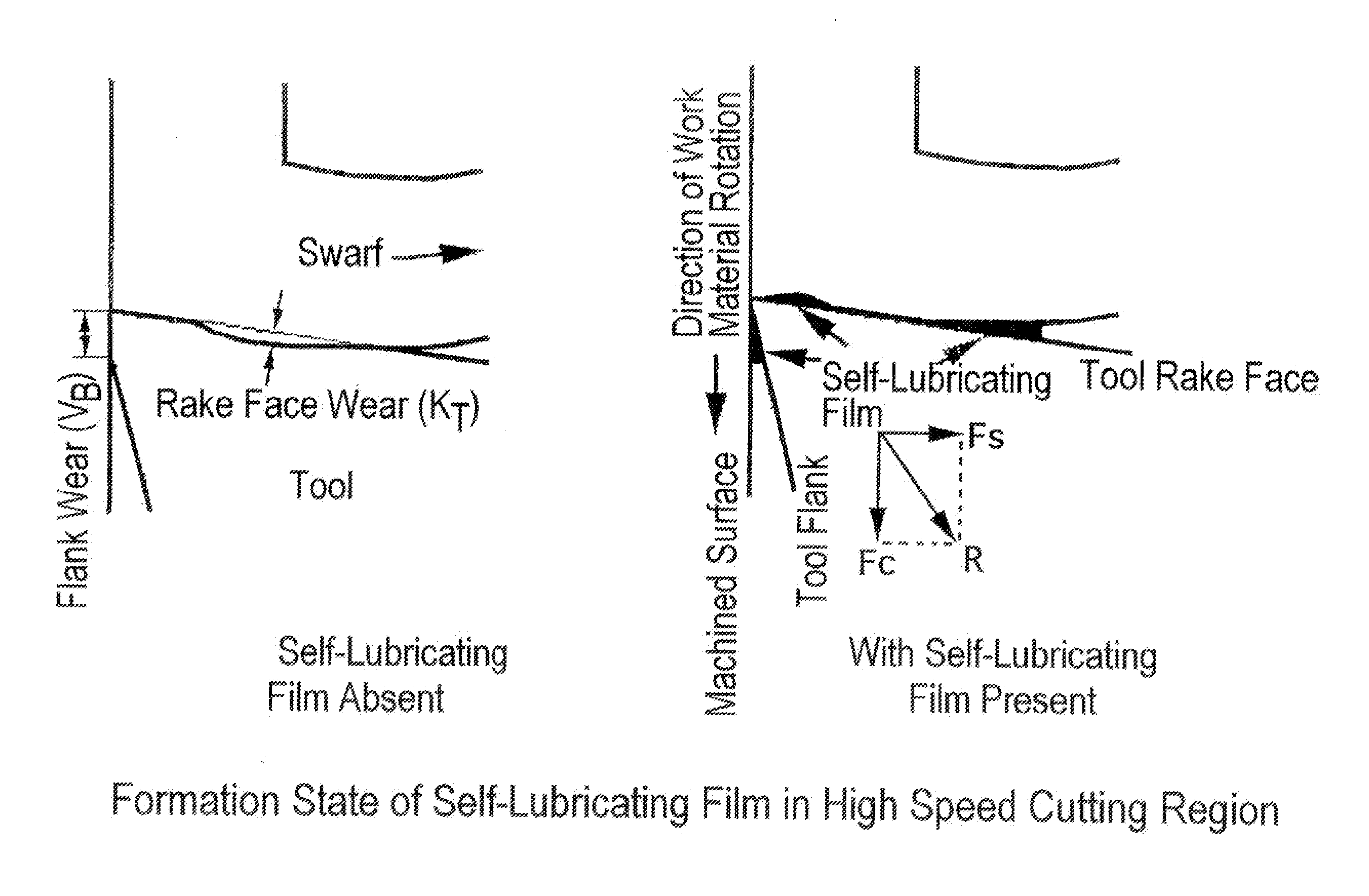
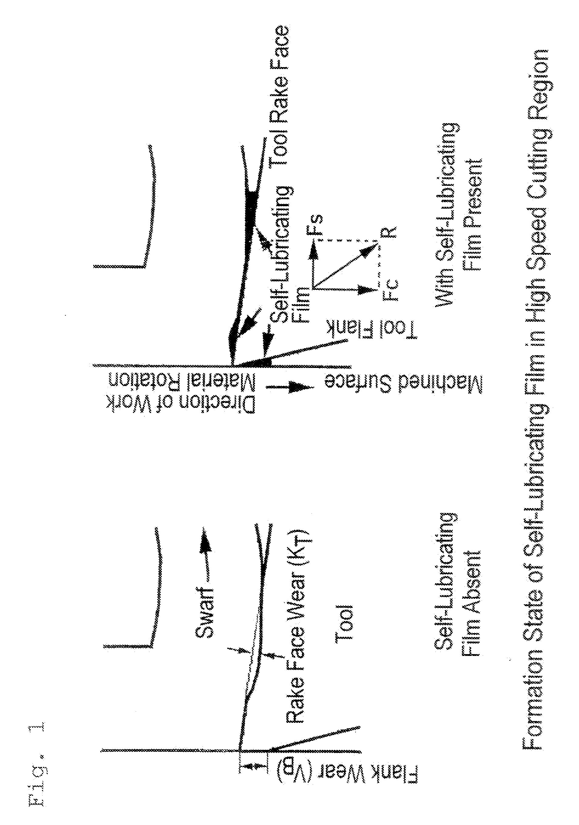
[0064] A force exerted on the tool during cutting, and the formation of a self-lubricating film are shown in FIG. 1.

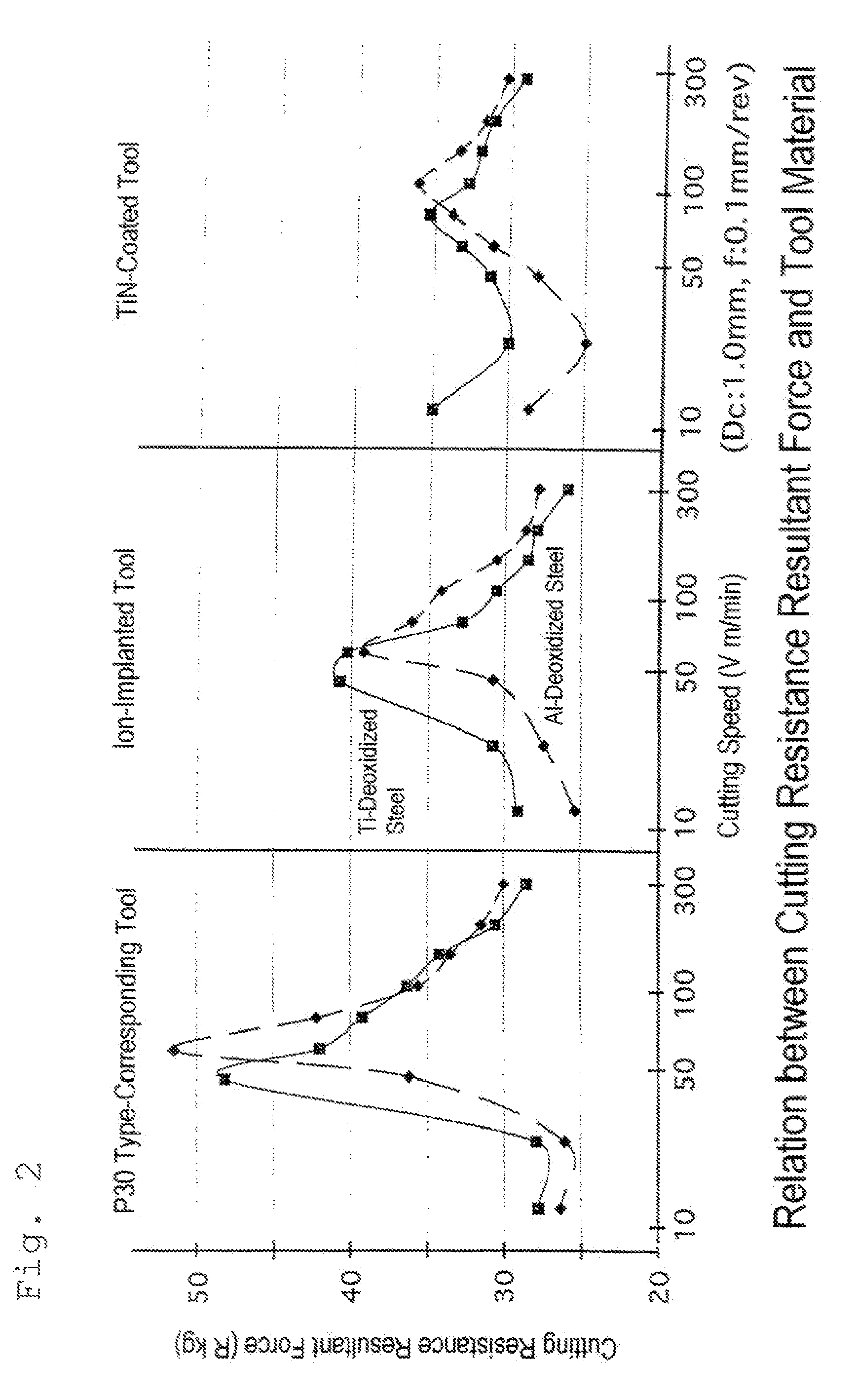
[0065]FIG. 2 shows the cutting speed dependence of a cutting resistance resultant force (R). All of the tools had maximum values in the medium speed region (40 ...

example 2

Wear Characteristics of Ion-Implanted Uncoated Tool

[0071] A wear test, by dry cutting, of the P10 ion-implanted tool was conducted. The conditions for the test are as follows: [0072] Cutting speed V: 50-250 m / min [0073] Cutting length: 500 m [0074] (Cutting time depends on the cutting speed: for example, it is 10 minutes at V=50 m / min, and 2 minutes at B=250 m / min) [0075] Work materials: Al-deoxidized steel and Ti-deoxidized steel described above

[0076] Other conditions were the same as those in Example 1.

[0077] The rake face wear depth (kT) and flank wear width (VB) of the tool after the test were measured to evaluate wear (FIG. 5). As shown in FIG. 5, when the Ti-deoxidized steel is used as the work material, kT and VB are smaller, and thus wear characteristics are improved.

example 3

Analysis of Self-Lubricating Film of Ion-Implanted Uncoated Tool

[0078] In connection with the ion-implanted P10 tool used in the same cutting as in Example 1, the resulting self-lubricating film was observed with an optical microscope (FIG. 6). As a result, the formation of the film on the surface of contact with the work material was noted.

[0079] The composition of the film was measured by XAM (FIGS. 7(a) to 7(d). As shown in FIGS. 7(a) to 7(d), Ti—Mn—Si compound oxides are formed in the vicinity of the surface of contact with the work material.

[0080] In FIGS. 7(a) to 7(d), W, Si, Mn, Al and Ti were measured in the film region, and their masses were calculated on the assumption that they would exist as WC, SiO2, MnO, Al2O3 and TiO2, respectively, and the sum of these masses was taken as 100%. The values of the mass % obtained for each compound based on this assumption were indicated for the respective elements in FIGS. 7(a) to 7(d). In regard to Ti, for example, the mass ration...


PUM

PropertyMeasurementUnit
Lengthaaaaaaaaaa
Lengthaaaaaaaaaa
Lengthaaaaaaaaaa

Abstract

Object: A high speed machining component, which has been improved in wear resistance and lubricating properties, and a high speed dry machining method using the component are provided. Particularly, a high speed cutting tool and a high speed cutting method are provided. Means for solution: A halogen element is ion-implanted into a machining component having a cemented carbide as a base material, and the machining component is contacted with a workpiece at a speed of 150 m/min or higher, whereby the wear resistance and lubricating properties of the component can be improved. If the machining component has a Ti-containing coating layer, its wear resistance and lubricating properties can be improved similarly. The use of a cutting tool including such a component enables high speed dry cutting without a cutting oil. By bringing the machining component of the present invention into contact with the workpiece at a high speed, a self-lubricating film can be formed on a surface of contact of the component with the work material.

Description

TECHNICAL FIELD [0001] This invention relates to a component which is excellent in wear resistance, lubricating properties, and fracture resistance, and can be used for high speed machining applications. The invention also relates to a machining tool including the component, and a high speed machining method, especially, a dry cutting method, using the tool. BACKGROUND ART [0002] In recent years, a high machining speed has been demanded from the viewpoint of increased productivity, and high speed cutting has been desired, for example, in the field of cutting. The range of targets for high speed cutting has been expanded, and there has been a demand for the application of high speed cutting to high hardness materials such as hot forging dies after hardening by heat treatment, and die casting molds. [0003] With conventional cutting methods, cutting oils were used for promoting a lubricating action and cooling a cutting edge, and cutting oils were needed, particularly, in high speed cu...

Claims


Application Information

Patent Timeline
IPC IPC(8): B22D7/00B23B27/10B23B27/14C23C14/48
CPCB23B27/10B23B27/14Y10T428/12B23B2228/10C23C14/48B23B2224/32
Inventor AIZAWA, TATSUHIKOMITSUO, ATSUSHI
Owner AIZAWA TATSUHIKO
Why Eureka
Try Eureka