Intramedullary nail system with tang fixation

a technology of intramedullary nail and fixation, which is applied in the field of intramedullary nail system, can solve the problems of affecting the patient's x-ray radiation, irritating the surrounding tissue, and additional time required under x-ray radiation exposure, and achieves the effect of preventing rotation

Inactive Publication Date: 2013-07-23
ORTHOPEDIC DESIGNS NORTH AMERICAN
View PDF15 Cites 28 Cited by
  • Summary
  • Abstract
  • Description
  • Claims
  • Application Information

AI Technical Summary

Benefits of technology

[0024]Next, the lag screw fixation type must be set. Regardless of whether compression is used, the lag screw must be set in either a fixed or sliding fixation type. A fixed lag screw position prevents both rotation and sliding of the lag screw relative to the nail body. A fixed position is achieved by fully tightening the lock screw button against the anti-rotation flat. A sliding lag screw position allows free lateral sliding of the lag screw, while preventing rotation. This is achieved by the l

Problems solved by technology

But rotation of the inserted nails was a problem because rotation would result in the nail being in a position different than that chosen by the surgeon.
These additional screws often had associated plates, changing the profile of the bone, potentially causing irritation to surrounding tissue

Method used


Image

  • Intramedullary nail system with tang fixation
  • Intramedullary nail system with tang fixation
  • Intramedullary nail system with tang fixation

Examples


Embodiment Construction

[0055]Reference will now be made in detail to the presently preferred embodiments of the invention, examples of which are illustrated in the accompanying drawings. Throughout the following detailed description, the same reference numerals refer to the same elements in all figures.

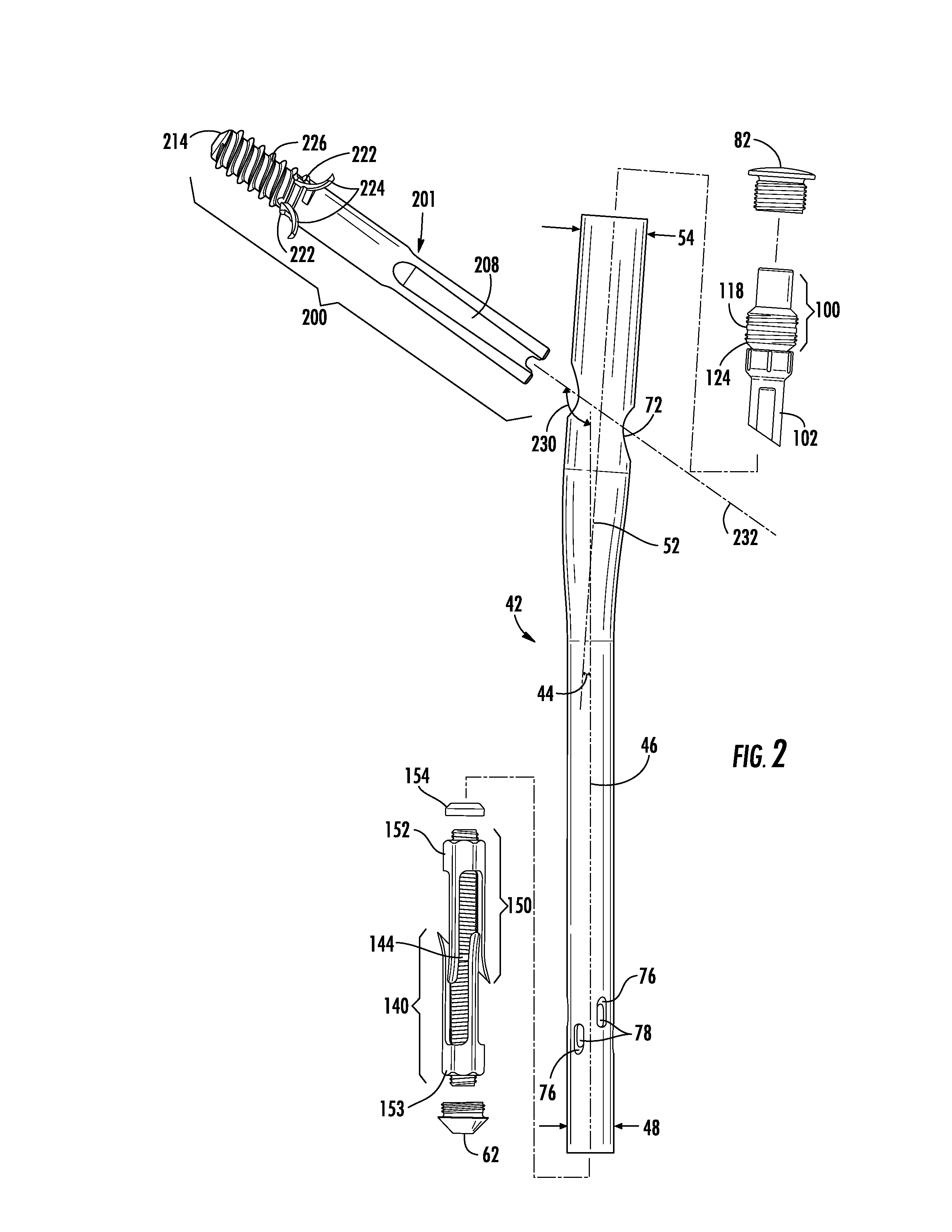
[0056]The individual components of the assembly, as illustrated, are constructed of implantable grade titanium, but it is anticipated that any suitable material be used, such as implantable grade stainless-steel alloys or polymeric materials such as nylon, carbon fibers, and thermoplastics.

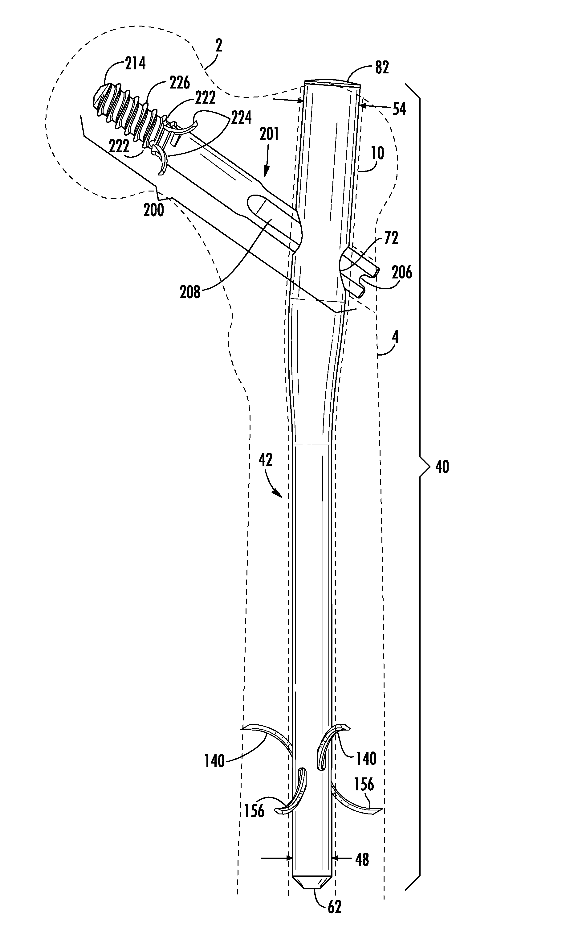
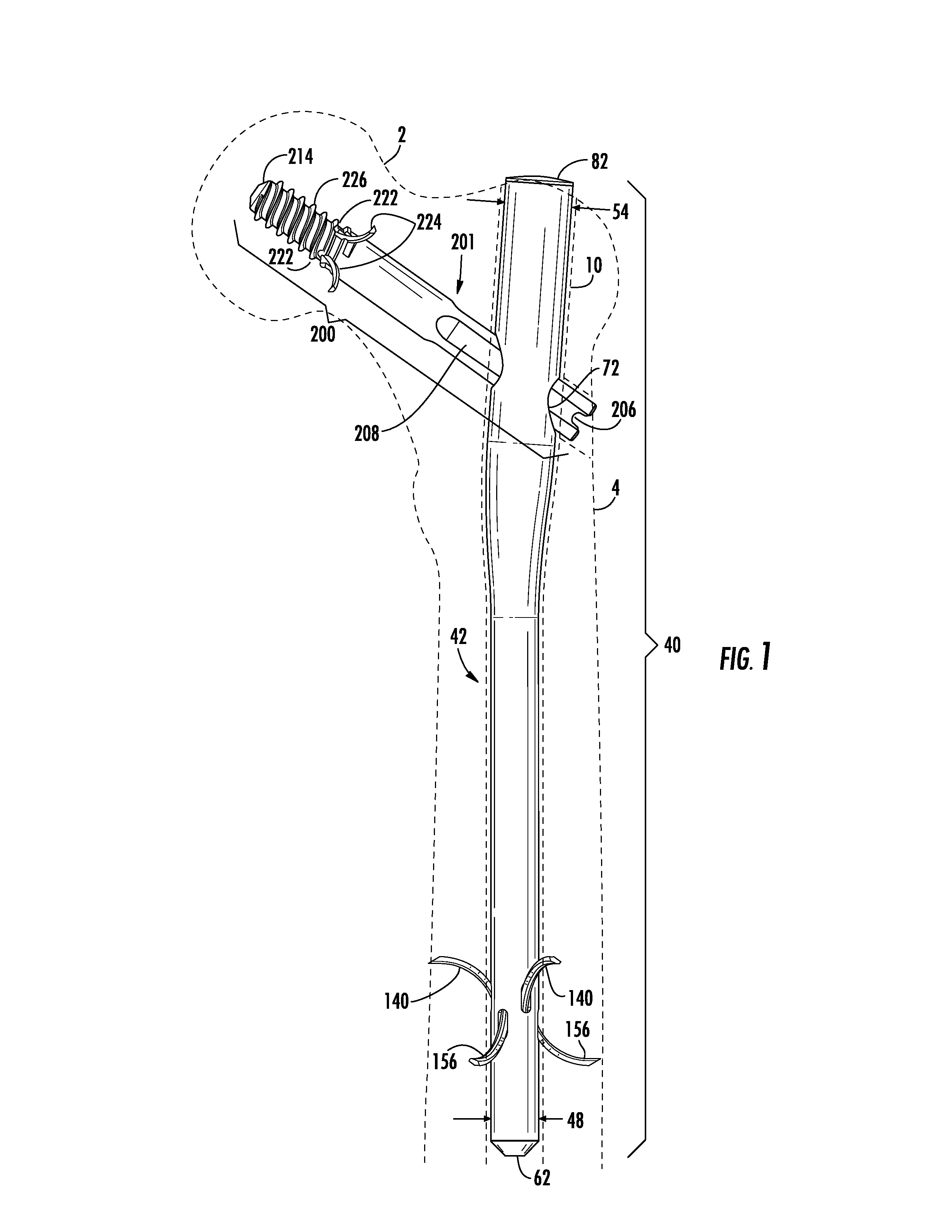
[0057]The Intramedullary Nail System with Tang Fixation disclosed is especially suited for use fixing / stabilizing stable and unstable fractures of the upper portion of the femur. Exemplary, but not exclusive, examples of such fractures include intertrochanteric fractures, pertrochanteric fractures, high subtrochanteric fractures, low subtrochanteric fractures, and combinations thereof.

[0058]Much of the disclosure within t...


PUM


Abstract

The Intramedullary Nail System with Tang Fixation includes a nail for insertion into the intramedullary canal of the femur and a lag screw for insertion through the nail, into the femoral head of the femur. The nail is affixed to the inside of the femur using only extendable tangs that extend into the bone. Similarly, the lag screw is secured to the inside of the femur and femoral head using only threads and extendable tangs. Thus, the nail is held within the intramedullary canal of the femur, affixed internally by the lag screw and tangs, without the use of screws that penetrate the surface of the bone, and without requiring significant x-ray exposure.

Description

RELATED PATENTS[0001]The disclosure of the following patents is hereby incorporated by reference: U.S. Pat. No. 5,976,139, issued Nov. 2, 1999; U.S. Pat. No. 6,183,474, issued Feb. 6, 2011; U.S. Pat. No. 6,443,954, issued Sep. 3, 2002; U.S. Pat. No. 6,447,546, issued Sep. 10, 2002; U.S. Pat. No. 6,448,684, issued Dec. 3, 2002; U.S. Pat. No. 6,648,889, issued Nov. 18, 2003; U.S. Pat. No. 6,695,844, issued Feb. 24, 2004.FIELD[0002]The present invention relates to an intramedullary system for coupling a first and second portion of bone across a fracture.BACKGROUND[0003]Intramedullary nails were first used in the 1930s. These early nails were inserted into the intramedullary canal of the femur. The result was immediate fixation of femur fractures, resulting in reduced patient recovery time, increased mobility, and increased quality of life. Multiple examples of such nails are present in the prior art.[0004]But rotation of the inserted nails was a problem because rotation would result in...

Claims


Application Information

Patent Timeline
IPC IPC(8): A61B17/72
CPCA61B17/7266A61B17/744
Inventor FAGAN, LANCE
Owner ORTHOPEDIC DESIGNS NORTH AMERICAN
Why Eureka
Try Eureka