Apparatus for manufacturing polymer resin, polymerization vessel, and method for manufacturing polymer resin

a technology of polymer resin and manufacturing apparatus, which is applied in the direction of transportation and packaging, chemical/physical/physico-chemical processes, and rotary stirring mixers. it can solve the problems of reducing the heat transfer area per unit volume of the polymerization vessel, the composition of a san thus produced is not uniform, and the manufacturing apparatus has been suffered a shortage of heat removal, so as to reduce the composition and temperature distribution of the polymer resin. , to prevent the bearing part from

Active Publication Date: 2013-07-23
TOYO ENG CORP
View PDF15 Cites 0 Cited by
  • Summary
  • Abstract
  • Description
  • Claims
  • Application Information

AI Technical Summary

Benefits of technology

[0047]In general, a monomer as a raw material of a polymer resin and other raw materials are kept at a low temperature, so as not to be polymerized within a monomer storage tank, within an injected raw material adjustment tank, and within a pipeline at any point thereof up to the polymerization vessel. This low-temperature raw material is prevented by the protection part and the flow path-constituting part from coming into contact with a polymerization solution present in the protruding part while flowing from the first flow path to the third flow path, and is in a state of having direct contact with the agitation axis. Here, if there are no such a protection part and a flow path-constituting part as mentioned in the above-described embodiment, the raw material and the polymerization solution which has circulated by way of the second cooling means, are directly mixed with each other immediately after being injected into the protruding part. Consequently, within the protruding part, there arises a portion of the polymerization solution having the composition and temperature which significantly differ from those of a polymerization solution within the main body. In contrast, in the manufacturing apparatus of the above-described embodiment, it is possible to instantaneously and uniformly mix the low-temperature raw material newly injected into the protruding part, a polymerization solution within the polymerization vessel, and a polymerization solution circulated by the circulating cooling means in a small region in the bottom of the polymerization vessel. As a result, it is possible to narrow the composition and temperature distributions of the polymer resin.
[0048]In addition, the raw material injected into the protruding part is heated by frictional heat generated by the rotation of the agitation axis at the bearing part, heat transferred from the polymerization solution having circulated within the second cooling means through the protection part, and heat transferred from within the polymerization vessel through the agitation apparatus. Consequently, the raw material is at a certain level of high temperature at the moment of flowing out of the uppermost end of the first flow path into the polymerization vessel. Accordingly, a difference in temperature between the raw material flowing out of the uppermost end of the first flow path and the polymerization solution becomes small. Thus, it is possible to even more uniformly mix and agitate the raw material and the polymerization solution. Furthermore, the heat of the bearing part can be removed by this low-temperature raw material. Consequently, it is possible to prevent the bearing part from becoming so excessively hot as to shorten the service life thereof, and a polymerization reaction from taking place in the vicinity of this part.
[0049]The protection part is formed so as to be opposite to the circulating inlet nozzle where the polymerization solution having passed through the second cooling means is injected into the protruding part. Accordingly, it is possible to prevent the agitation axis from fluctuating laterally due to the liquid pressure of the circulated polymerization solution caused when the solution is injected into the protruding part.
[0050]As described heretofore, it is possible to cause a polymerization reaction to take place uniformly within the polymerization vessel. Thus, it is possible to manufacture a polymer resin having a uniform composition in a stable manner over a prolonged period of time.

Problems solved by technology

However, the manufacturing apparatus disclosed in Japanese Patent Publication Nos. 47-610, 55-35912 and 48-29628, in some cases, fails to fully and uniformly perform the mixing and copolymerization reaction of a raw material and a polymerization solution, resulting in a nonuniform composition of a SAN thus produced.
As a result, the manufacturing apparatus has been suffered a shortage of heat removal since a heat transfer area per the unit volume of the polymerization vessel decreases due to an increase in the size of the apparatus.
Accordingly, the apparatus of Japanese Patent Publication No. 47-610 has been considered not fully adaptable to an increase in size.
Japanese Patent Publication No. 55-35912 does not specifically disclose any methods for injecting a raw material into the polymerization vessel and mixing and agitating the raw material.
Furthermore, in a case where the polymerization solution within the polymerization vessel is circulated through an external cooler as in this manufacturing apparatus, the manufacturing apparatus, in some cases, has been affected adversely in such a manner that the agitation axis of an agitation apparatus within the polymerization vessel fluctuates laterally due to the liquid pressure of this circulated polymerization solution when the circulated polymerization solution is fed back into the polymerization vessel.
Consequently, if the apparatus is directly increased in size, as described above, it is not possible to fully remove the heat of polymerization, thus requiring a cooler to be provided externally.

Method used


Image

  • Apparatus for manufacturing polymer resin, polymerization vessel, and method for manufacturing polymer resin
  • Apparatus for manufacturing polymer resin, polymerization vessel, and method for manufacturing polymer resin
  • Apparatus for manufacturing polymer resin, polymerization vessel, and method for manufacturing polymer resin

Examples


first embodiment

(First Embodiment)

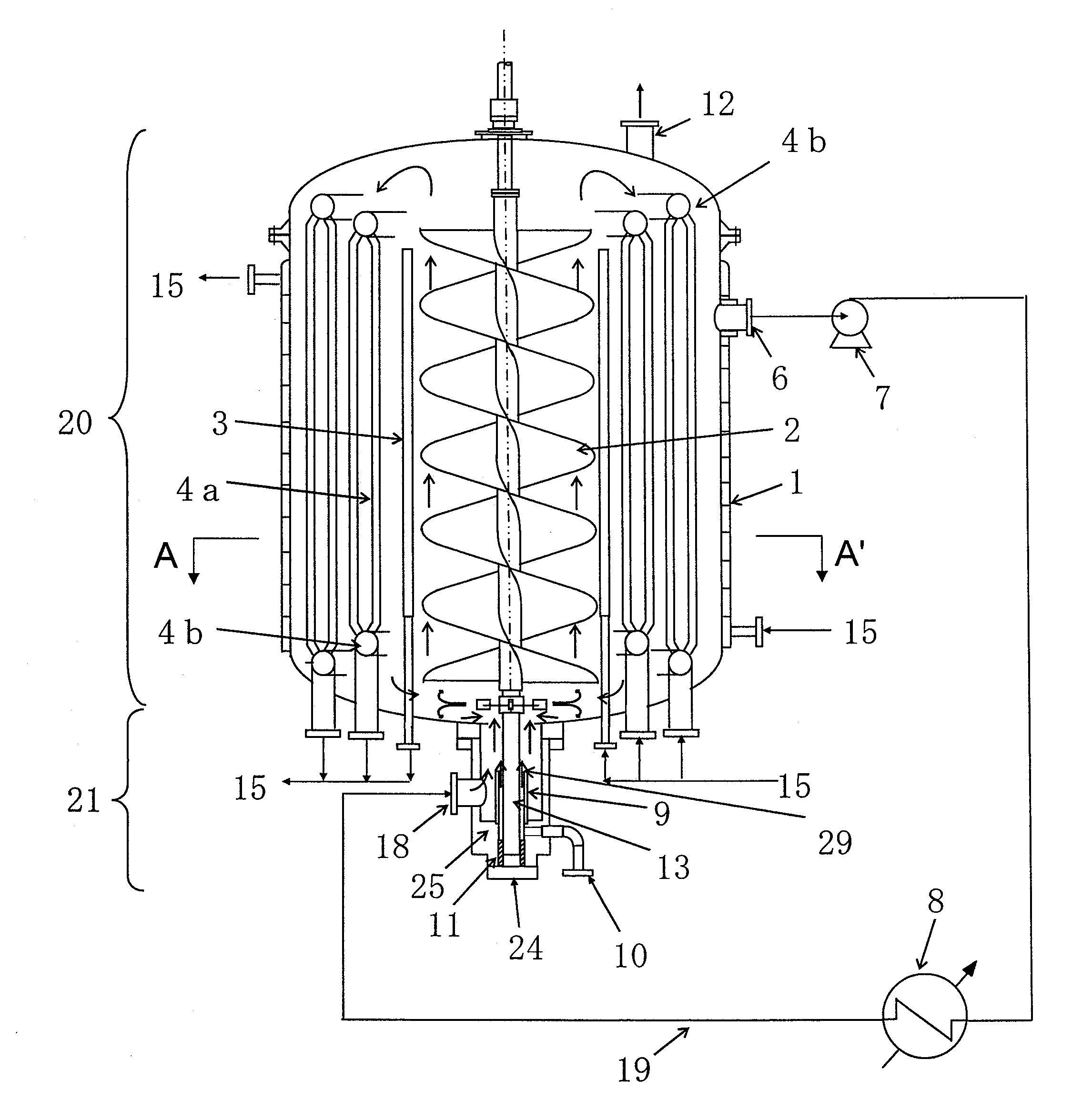
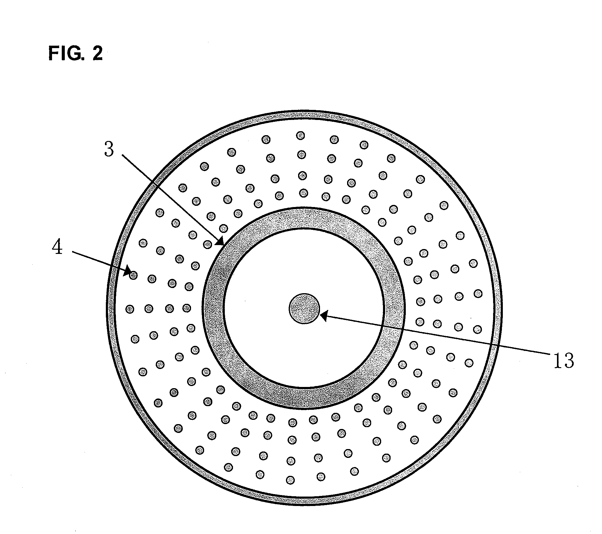
[0067]FIGS. 1 and 2 illustrate one example of a manufacturing apparatus according to the present invention. FIG. 1 represents a side cross-sectional view of this manufacturing apparatus and FIG. 2 represents a cross-sectional view taken along the line A-A′ of the manufacturing apparatus illustrated in FIG. 1 (FIG. 2 represents only the basic configuration of the manufacturing apparatus illustrated in FIG. 1, and part of the structure thereof is excluded from the figure. In addition, the white area on the black background represents a portion filled with a polymerization solution). This manufacturing apparatus is formed with a polymerization vessel including main body 20 and protruding part 21 protruding downwardly from the bottom face of the main body. The lower part of this protruding part 21 is composed of bottom cover 24.

[0068]Above the main body of this polymerization vessel, there is installed an unillustrated driving part. In addition, agitation axis 13 is co...

second embodiment

(Second Embodiment)

[0115]The present embodiment relates to a pressure-releasing part for runaway polymerization reaction within a polymerization vessel. FIG. 6 illustrates one example of this manufacturing apparatus. In the present embodiment, unlike the first embodiment, the manufacturing apparatus includes rupture disk 5 in the upper part of main body 20 as a pressure-releasing part to be opened so as to depressurize the inside of the polymerization vessel when the internal pressure of the polymerization vessel is or exceeds a predetermined pressure. A nozzle and a depressurization apparatus, such as a remote-operated valve, may be formed as the pressure-releasing part in place of rupture disk 5. In addition, circulation pipeline 19 is connected to the side face of main body 20, and a height between the tangent line (TL) of main body 20 and the uppermost end of the inner wall of circulation pipeline 19 is 0.2 D or greater but not greater than 0.5 D, assuming the inner diameter of ...

third embodiment

(Third Embodiment)

[0122]The third embodiment shows one example in which a copolymer resin is used as a polymer resin. Many of copolymer resins feature rapid copolymerization reaction and high reaction heat. Thus, the copolymer resins have the characteristic that the internal temperature of the polymerization vessel tends to become high, and a temperature distribution within the polymerization vessel tends to become nonuniform. Accordingly, by using the manufacturing apparatus in accordance with the present invention, it is possible to remove the heat of polymerization generated by the reaction heat of the copolymerization reaction within the polymerization vessel and uniformly control the internal temperature of the polymerization vessel to within a desired temperature range. In addition, by injecting a low-temperature raw material for copolymer resin into the protruding part, it is possible to maintain the bearing part and the agitation axis at a low temperature. As a result, it is...


PUM

PropertyMeasurementUnit
temperatureaaaaaaaaaa

Abstract

An apparatus for manufacturing a polymer resin comprises a polymerization vessel, a bearing part, a protection part, a circulating cooling means, a raw material-injecting nozzle and a flow path-constituting part. The protection part forms a first flow path between the protection part and the side face of the agitation axis. The circulating cooling means includes a circulating inlet nozzle provided on a side face of the protruding part so as to be opposite to the protection part. The flow path-constituting part is provided between the bearing part and the protection part so as to cover the side face of the agitation axis, to fix the bearing part and the protection part. This flow path-constituting part forms a second flow path between the side face of the agitation axis and the flow path-constituting part and a third flow path for coupling the second flow path with the raw material-injecting nozzle. The first to third flow paths constitute a continuous flow path and an uppermost end of the first flow path is opened to the inside of the protruding part. The gap, part of the first flow path other than the uppermost end, the second flow path and the third flow path are isolated from the inside of the protruding part.

Description

[0001]This application is the U.S. National Phase under 35. U.S.C. § 371 of International Application PCT / JP2008 / 066837, filed Sep. 18, 2008. The International Application was published under PCT Article 21(2) in a language other than English.TECHNICAL FIELD[0002]The present invention relates to an apparatus and a method for manufacturing a polymer resin. Preferably, the present invention relates to a manufacturing apparatus and a manufacturing method used to manufacture a highly transparent resin, such as a styrene-acrylonitrile copolymer resin (SAN) and a methyl methacrylate-styrene copolymer resin (MS) which are copolymer resins.BACKGROUND ART[0003]Conventionally, a styrene-acrylonitrile copolymer resin (hereinafter occasionally described as “SAN”) has been manufactured on an industrial scale. This SAN is manufactured in a continuous manner for reasons of improvement in productivity or the like.[0004]On the other hand, the SAN is manufactured by the copolymerization reaction of s...

Claims


Application Information

Patent Timeline
Patent Type & Authority Patents(United States)
IPC IPC(8): C08F2/04B01J19/18B01F5/06C08F220/44
CPCB01F5/10C08F2/01B01F7/18B01F7/24B01F15/066B01J4/002B01J19/0013B01J19/0066B01J19/1875B01F7/0065B01F2015/061B01J2204/002B01J2219/00081B01J2219/00083B01J2219/00094B01J2219/0011B01F25/50B01F27/1921B01F27/92B01F27/90B01F35/93B01F2035/98C08F212/10C08F2/00B01J19/00
Inventor MATSUBA, KENICHIROUKIMURA, KAZUSHIGE
Owner TOYO ENG CORP
Why Eureka
Try Eureka