Electromagnetic signal power limiter and method of designing the power limiter

a technology of power limiter and electromagnetic signal, which is applied in the direction of limiting amplitude without controlling loop, limiting amplitude, electrical apparatus, etc., can solve the problems of goniometry and/or signal source locating processing operations, no longer being used by digital processing subsystems, and distortion of signals

Active Publication Date: 2013-07-23
THALES SA
View PDF6 Cites 5 Cited by
  • Summary
  • Abstract
  • Description
  • Claims
  • Application Information

AI Technical Summary

Benefits of technology

[0091]that it allows a power limiter to be designed by precisely controlling its physical constitution in order to control the limiting characteristics of said limiter;
[0092]that it allows the limiter according to an embodiment of the invention to operate in degraded mode without limiting its performance levels;

Problems solved by technology

However, such a limiter has the major drawback of distorting the signals to the point that they can no longer be used by the digital processing subsystems.
Furthermore, the goniometry and / or signal source locating processing operations then become inoperative.
New generations of wireless communication terminals are therefore faced with increasingly difficult problems associated with three types of antinomic constraints:the first constraint is to detect, recognize and use signals that are increasingly varied in terms of power and frequency, notably for all types of emissions, in all the wavelength bands, for the most diverse radiocommunication sets, from tactical sets to portable telephones, and do so over a very wide band spanning a few hundreds of megahertz to several gigahertz;a second constraint is to be protected against signal interferences, the peak power of which will increase in time given the current technical developments;a third constraint is to accurately locate in space, to within a fraction of a degree for example, all the sources emitting electromagnetic signals by wide band interferometry techniques.
A saturation of the receiving subsystems leads to a loss of the signals, in which case a processing of the signal phases is pointless.
This type of function does not currently exist, notably because the receivers are sensitive to saturation, even when they are protected by current power limiting devices.
Although very commonly used, the current limiters have a major drawback: their poor performance levels in the hyper frequency domain.
In practice, the insertion losses of the current limiters are high, notably greater than 1 dB.
Such insertion losses are not optimal for certain specific applications in which the signals are very low in amplitude.
Furthermore, the resistance of the current limiters in terms of received power is limited to a few tens of watts.
Overheating induced by the passage of the current during incident signal power limiting phases may lead to destruction of the components situated downstream of a current limiter.
Such solutions are therefore difficult to integrate with other technologies.
Solutions based on ferroelectric and magnetic materials may be envisaged but cannot be fabricated inexpensively by collective methods.
Furthermore, their performance levels in the hyper frequency domain and their power resistance over time remain uncertain.
Similarly, solutions based on ferrites or plasma lines have been published, and some are used in specific equipment, such as nuclear instrumentation for example, but, generally, they meet only one of the limiter specifications well, and meet the others unsatisfactorily.
The current solutions therefore do not meet the necessary specifications for a limiter.

Method used


Image

  • Electromagnetic signal power limiter and method of designing the power limiter
  • Electromagnetic signal power limiter and method of designing the power limiter
  • Electromagnetic signal power limiter and method of designing the power limiter

Examples


Embodiment Construction

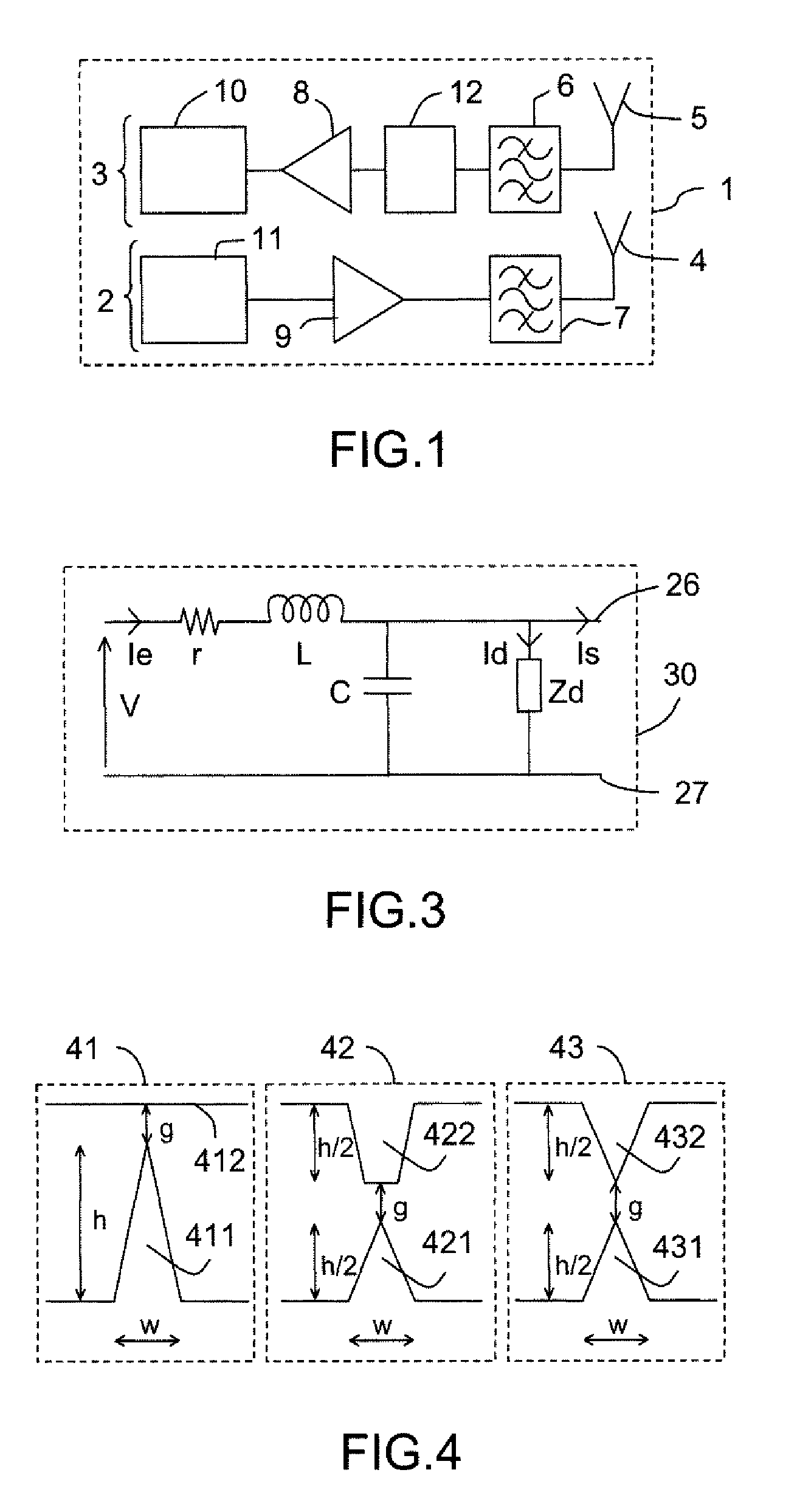
[0116]FIG. 1 represents a known radiofrequency transmission subsystem 1. The radiofrequency transmission subsystem 1 notably comprises a first transmission subsystem 2 and a second reception subsystem 3. Each subsystem, transmission 2 or reception 3, comprises:[0117]an antenna 4, 5;[0118]a filter 6, 7;[0119]an amplifier 8, 9.

The transmission subsystem 2 comprises a transmitter 11. The reception subsystem 3 comprises a receiver 10. A limiter 12 is, for example, placed on the reception subsystem 3 between a first filter 6 and a first amplifier 8. The limiter 12 can, in another embodiment, be placed between the antenna 5 and the first filter 6. The limiter 12, duly placed on the reception subsystem 3, can be used to avoid saturation or disabling, notably of the first amplifier 8 and of the receiver 10.

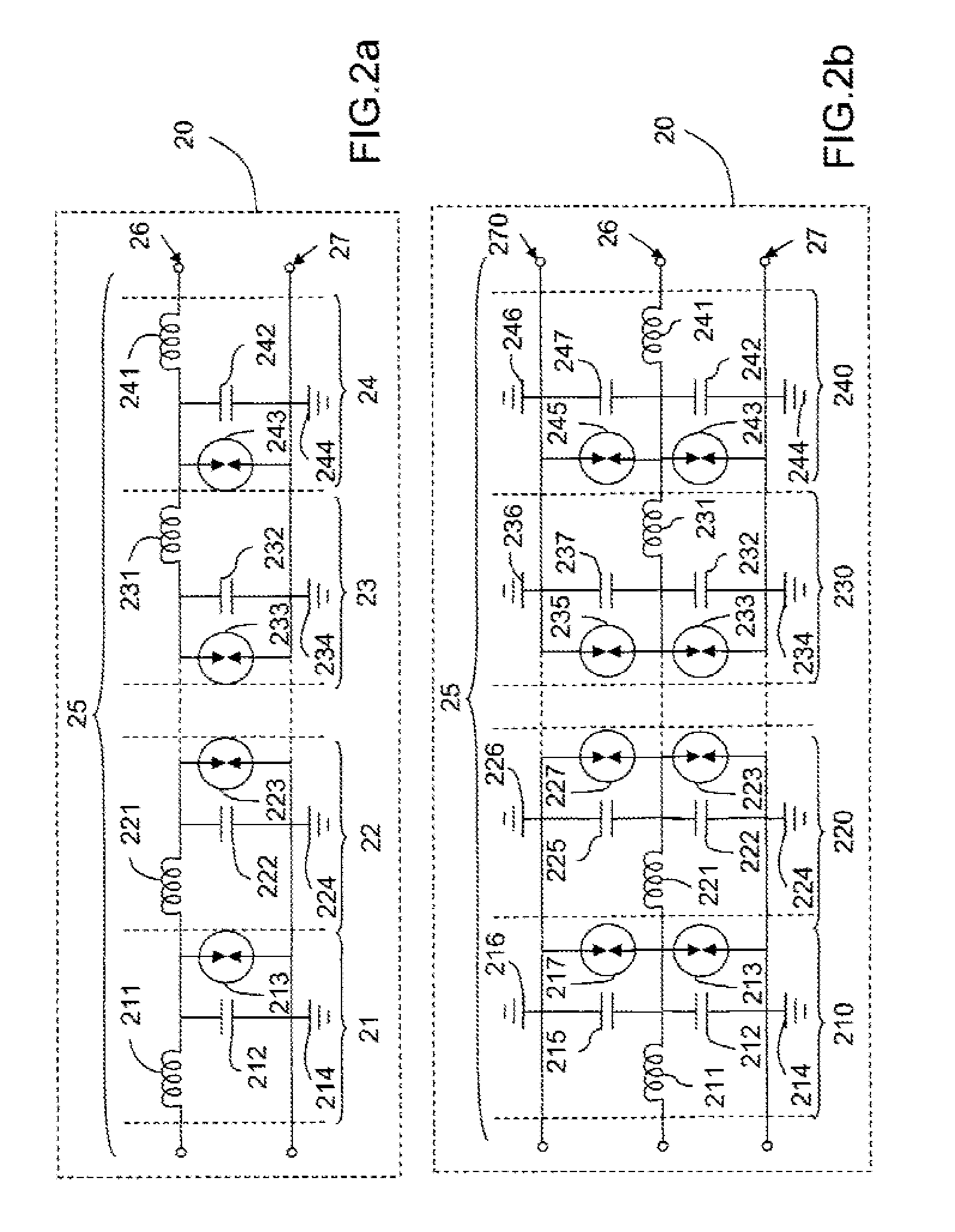
[0120]FIGS. 2a and 2b represent schematic diagrams of a distributed limiter 20.

[0121]FIG. 2a represents in particular a distributed limiter 20, suitable for an implementation using a micr...


PUM


Abstract

The present invention relates to an electromagnetic signal power limiter and its design method. The power limiter for an electromagnetic signal includes at least one transmission line for the signal. The transmission line is made up of a number of passive micro-diodes with ballistic electron transport. The micro-diodes are distributed on the transmission line, and are implemented in a controlled atmosphere. The invention applies notably to radiofrequency or hyperfrequency waves received by detection and communication devices.

Description

CROSS REFERENCE TO RELATED APPLICATIONS[0001]This application is the U.S. National Phase application under 35 U.S.C. §371 of International Application No. PCT / EP2008 / 066372, filed Nov. 27, 2008, and claims the benefit of French Patent Application No. 0708291, filed Nov. 27, 2007, all of which are incorporated by reference herein. The International Application was published on Jun. 4, 2009 as WO 2009 / 068632.FIELD OF THE INVENTION[0002]The present invention relates to an electromagnetic signal power limiter, notably for radiofrequency or hyper frequency waves received by detection and communication devices. The invention also relates to a method of designing the power limiter according to the invention.BACKGROUND[0003]Applications based on detections and communications by radiofrequency or hyper frequency waves require the capability to process electromagnetic signals that have significant dynamics. Examples of such applications are systems receiving electromagnetic waves, such as rad...

Claims


Application Information

Patent Timeline
Patent Type & Authority Patents(United States)
IPC IPC(8): H01P1/22
CPCH03G11/002H03G11/004
Inventor NICOLE, PIERREPHOMMAHAXAY, ALAINLISSORGUES, GAELLE
Owner THALES SA
Why Eureka
Try Eureka