Illumination optical apparatus, exposure apparatus, and device manufacturing method

a technology of exposure apparatus and optical apparatus, which is applied in the direction of photomechanical treatment, printing, instruments, etc., can solve the problems of lowering the imaging capability of the projection optical system, and achieve the effect of desired profil

Active Publication Date: 2013-07-23
NIKON CORP
View PDF25 Cites 0 Cited by
  • Summary
  • Abstract
  • Description
  • Claims
  • Application Information

AI Technical Summary

Benefits of technology

[0008]An embodiment of the present invention to provide an illumination optical apparatus that enables the desired profile to be maintained even when changing the outer shape of the light intensity distribution at the illumination pupil plane when using an axicon system. Another embodiment of the present invention is to provide an exposure apparatus capable of performing satisfactory exposure under proper illumination conditions using an illumination optical apparatus that changes the outer shape of the light intensity distribution formed at the illumination pupil plane while maintaining a substantially desired profile.
[0013]A fourth embodiment of the present invention is an illumination optical apparatus for use in an exposure apparatus for exposing a predetermined pattern onto a substrate. The illumination optical apparatus includes an optical system which changes light intensity distribution on an illumination pupil. A correction member corrects blurring of the light intensity distribution on the illumination pupil formed by the optical system.

Problems solved by technology

Such light would be shielded and become stray light thereby lowering the imaging capability of the projection optical system.

Method used


Image

  • Illumination optical apparatus, exposure apparatus, and device manufacturing method
  • Illumination optical apparatus, exposure apparatus, and device manufacturing method
  • Illumination optical apparatus, exposure apparatus, and device manufacturing method

Examples


Embodiment Construction

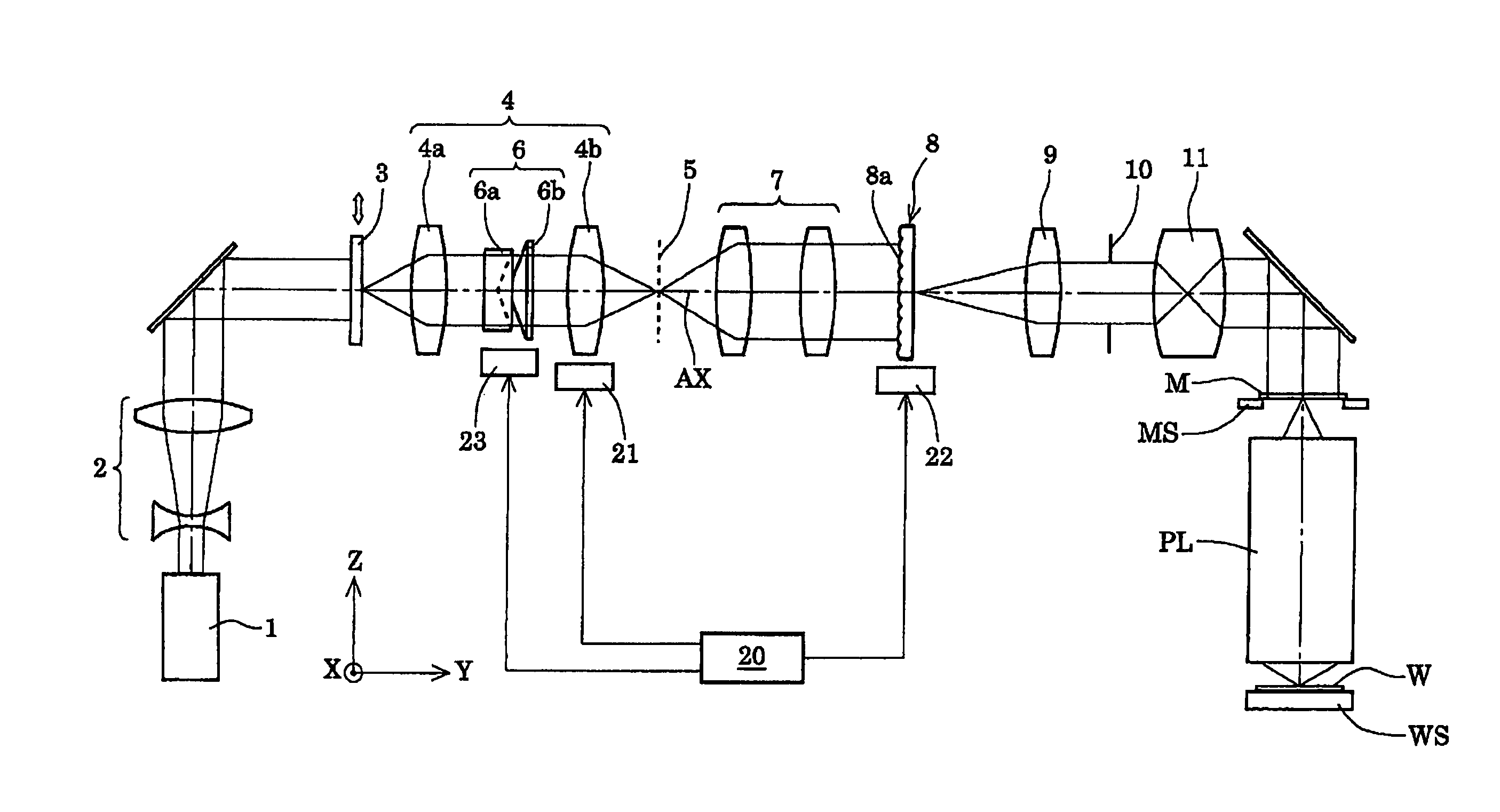
[0026]One embodiment of the present invention will now be discussed with reference to the accompanying drawings. FIG. 1 is a schematic diagram showing the structure of an exposure apparatus according to one embodiment of the present invention. In FIG. 1, the Z axis is set along a normal direction of a wafer W, which is a photosensitive substrate, the Y axis is set in a direction parallel to the plane of FIG. 1 in the plane of the wafer W, and the X axis is set in a direction perpendicular to the plane of FIG. 1 in the plane of the wafer W.

[0027]With reference to FIG. 1, the exposure apparatus of the present embodiment includes a light source 1 for supplying exposure light (illumination light). An ArF excimer laser light source for supplying light of wavelength 193 nm, a KrF excimer laser light source for supplying light of wavelength 248 nm, and the like may be used as the light source 1. A shaping optical system 2 enlarges the light emitted from the light source 1 to light having a...


PUM


Abstract

An illumination optical apparatus that substantially maintains a desirable profile even when changing the outer shape of light intensity distribution formed on an illumination pupil plane with an axicon system. The illumination optical system illuminates an irradiated surface based on light from an optical source and includes a prism system, which changes the interval along an optical axis between a pair of prisms to change the light intensity distribution on an illumination pupil plane.

Description

CROSS-REFERENCE TO RELATED APPLICATIONS[0001]This application is based upon and claims the benefit of priorities from International Application No. PCT / JP2007 / 055237 filed on Mar. 15, 2007, and Japanese Patent Application No. 2006-086322 filed on Mar. 27, 2006, the entire contents of which are incorporated herein by reference.BACKGROUND OF THE INVENTION[0002]The present invention relates to an illumination optical apparatus, an exposure apparatus, and a device manufacturing method, and more particularly, to an illumination optical apparatus suitable for use as an exposure apparatus that manufactures devices such as semiconductor device and a liquid crystal display device in a lithography process.[0003]In this type of typical exposure apparatus, light emitted from a light source passes through a fly's eye lens (or micro-lens array), which serves as an optical integrator, and forms a secondary light source, which serves as a substantial planar light source formed by many light sources...

Claims


Application Information

Patent Timeline
Patent Type & Authority Patents(United States)
IPC IPC(8): G03B27/54G03B27/42
CPCG02B5/001G03F7/70183G03F7/70108G03F7/70091G03F7/7015G03F7/70191G03F7/7055
Inventor TANAKA, HIROHISA
Owner NIKON CORP
Why Eureka
Try Eureka