Surgical templates

a surgical and template technology, applied in the field of surgical template systems, can solve the problems of increasing the complexity and time of the implantation procedure, increasing the number of intra-operative decisions, and inaccuracy in placement, so as to achieve cost-effectiveness, less complex, and shorter time

Active Publication Date: 2013-07-30
XIROS LTD
View PDF36 Cites 14 Cited by
  • Summary
  • Abstract
  • Description
  • Claims
  • Application Information

AI Technical Summary

Benefits of technology

[0012]As the locating means and tool guide block are separate from one another (and must be assembled and attached together to use the template) they can be manufactured separately and this provides a number of advantages. Firstly the tool guide block may be manufactured as a hard-wearing, reusable component that is not patient-specific. It can, for example, be manufactured from a metal, such that the guide apertures have hard metal surfaces which can guide a moving tool (such as a vibrating or reciprocating saw blade or rotating drill bit) without shedding material. The locating means can be made separately, by different techniques and, for example, using different material. For example, the locating means may be manufactured using rapid prototyping techniques so as to be patient-specific, based on a predetermined bone shape, that is a bone shape, topography or geometry that has been determined by a suitable technique on the patient, such as by scanning (which may also be referred to as imaging). Thus, a patient-specific system can be produced by rapid prototyping of just the locating means, and not the tool guide block. This helps speed up the process and also, reduces costs. In other words, embodiments of the invention offer the advantage that just some parts of the template system need be patient-specific, with other parts being “standard” i.e. predetermined and possibly reusable components. Advantageously, as the guide aperture or apertures are provided in the tool guide block and not in the patient-specific “custom” locating means, material can be used for the locating means that is suited to the patient-specific manufacturing technique (for example it may be a relatively soft plastic) whilst avoiding the problem of locating means material shedding during use, as the tools are guided by the guide block apertures.

Problems solved by technology

Disclosed positioning blocks sit on articular surfaces of bones, and this may lead to inaccuracies in placement.
This is disadvantageous because it is likely to increase both the complexity and time of the implantation procedure and adds to the number of intra-operative decisions to be made by the surgeon.
Furthermore, the apparatus of the template system itself and the associated tracking equipment is complex and costly.
Adjustable mechanisms are more expensive to manufacture than fixed, non-adjustable systems, are more prone to failure, and are harder to clean after use.
This can lead to inaccuracies in placement.
In the disclosed systems in which the instrument guide blocks sit directly on top of the moulded parts, a problem is how to fasten the guide block to the mold so as not to come apart whilst the bone cuts are made.
Positioning the instrument guide block on top of (over) a custom mold can move a guide aperture away from the bone surface, and can thus result in reduced accuracy when using that aperture to guide a cut.
The tibial and femoral devices sitting over the articular surfaces restrict the visibility of the surgeon whilst performing the bone cuts.
A flexible mold cannot be used to provide rigid location for an instrument guide block, and hence further inaccuracies in cutting the bone are introduced.
However, disadvantages of the disclosed templates include the following.
The relatively soft material used to form each of the single unit templates, and which therefore forms the walls of the guide apertures, readily sheds particulate material when in contact with moving tool bits (e.g. saw blades, drill bits), which is unacceptable as it might in the long term have an undesirable toxic effect on the tissues of a patient.
Further, the particulate matter might cause damage to the plastic prosthetic component if, trapped between the two prosthetic components while they are in use.
Friction between the moving surgical tools and the device can cause further shedding of particulate material from the device and would generate sufficient heat that can melt DuraForm™ under normal operating conditions.
This melting of the device material can cause seizure of the cutting tool.
It is now possible to rapid prototype customized devices using stainless steel resulting in non-porous devices.
However, constructing each device as a single unit, for the purpose of single use is extremely expensive and this option is therefore not likely to be cost effective.
Lastly, the templates disclosed in the paper are relatively bulky, and substantially reduce visibility of the femur and tibia being worked on.

Method used


Image

  • Surgical templates
  • Surgical templates
  • Surgical templates

Examples


Embodiment Construction

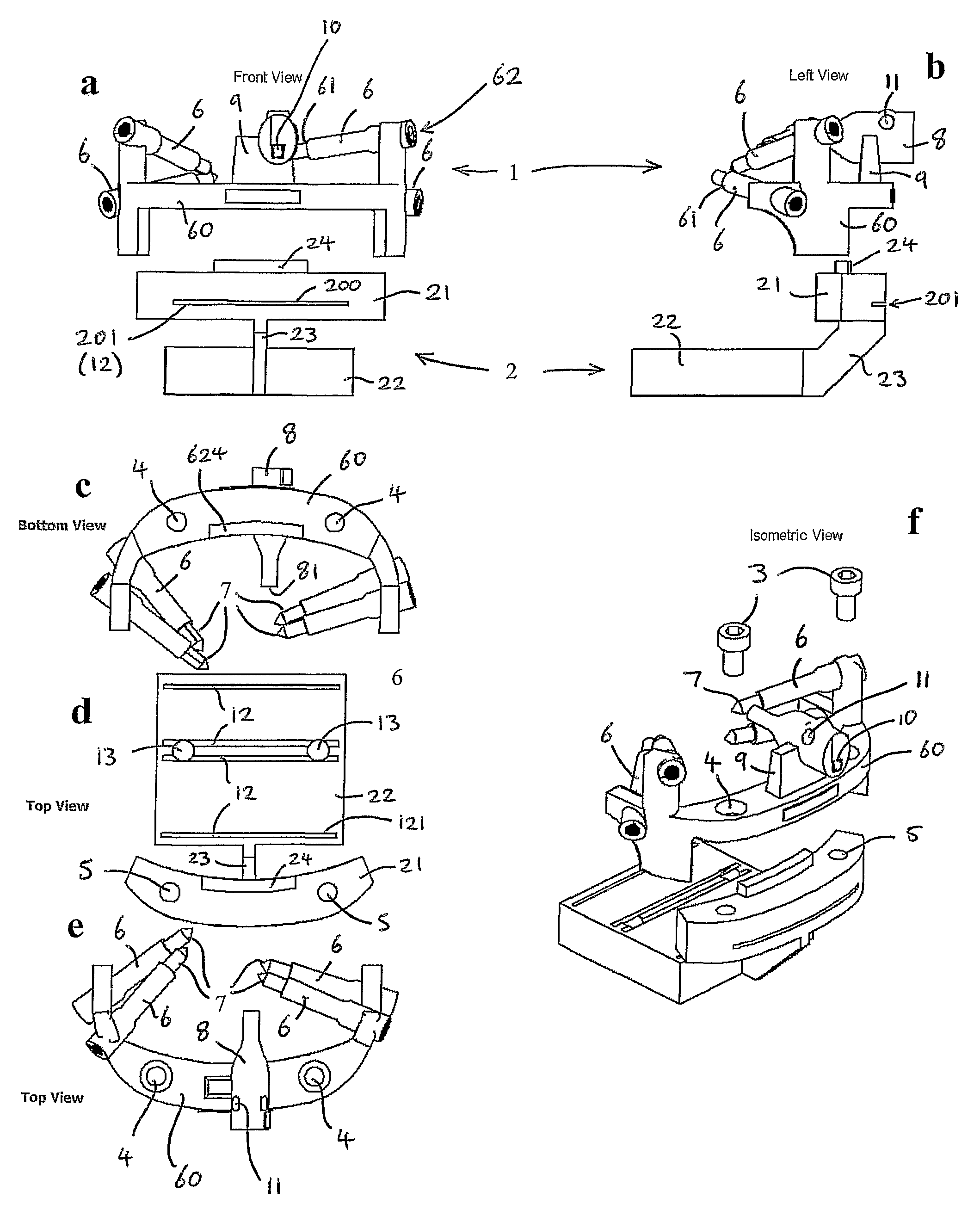
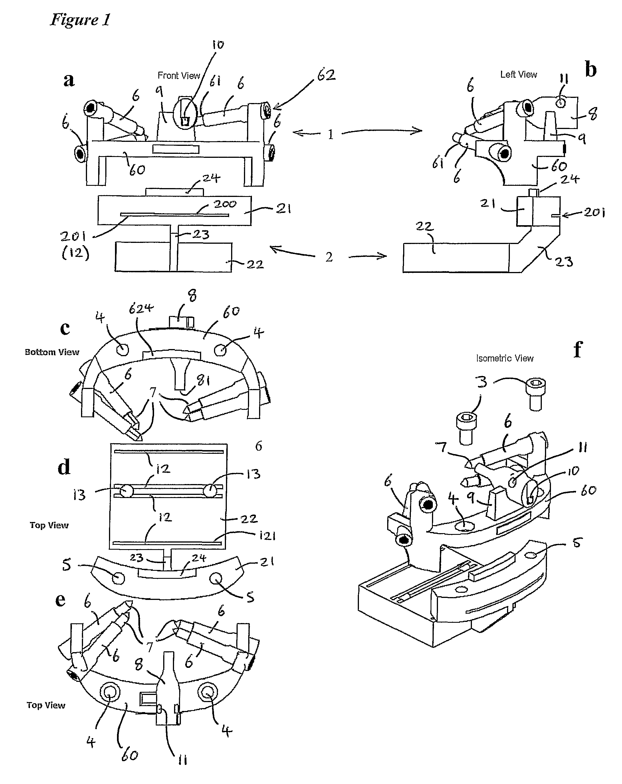
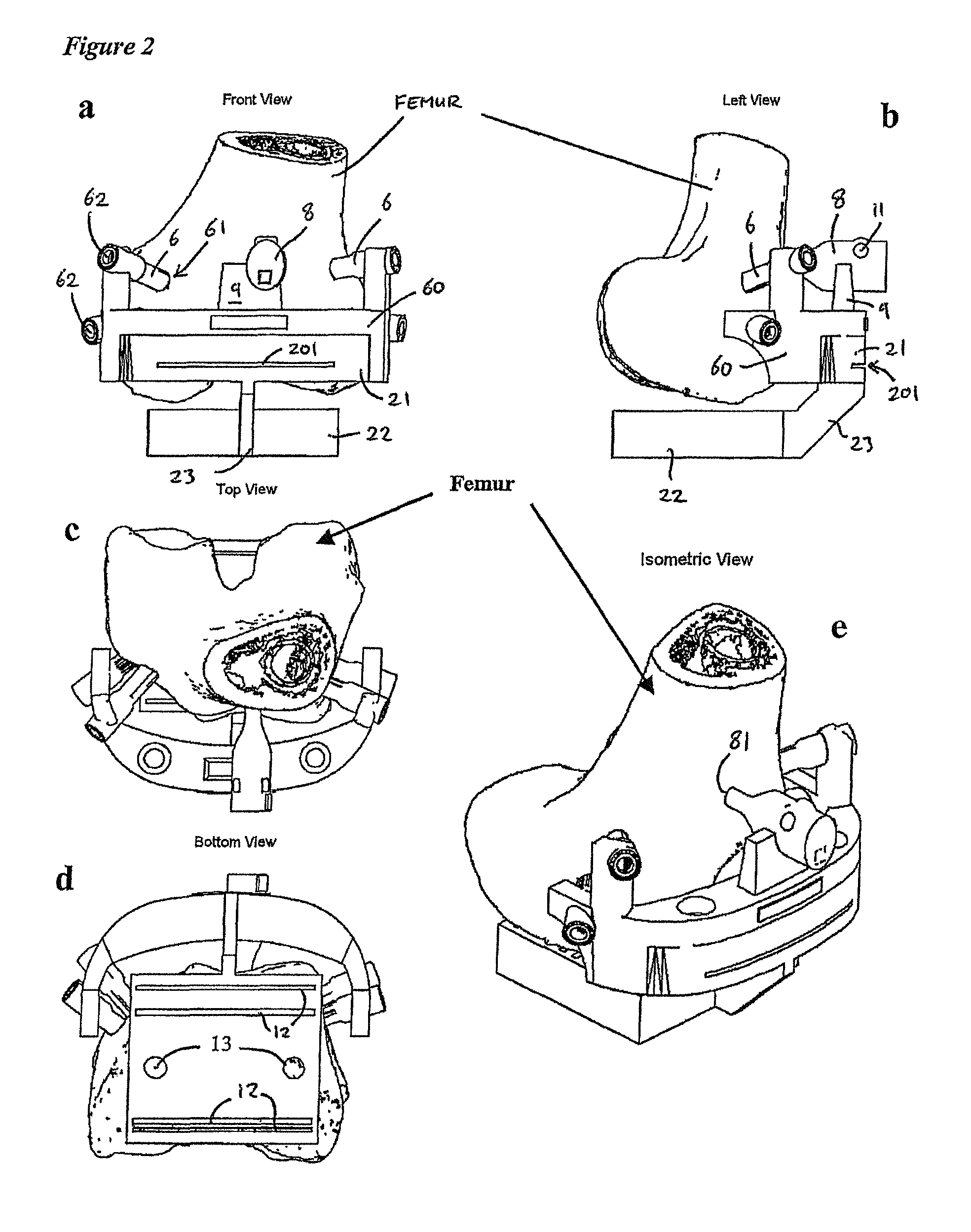
[0139]Certain embodiments of the invention may be used in the field of total knee replacement (TKR) surgery. In one example of TKR surgery, two different assemblies each embodying the invention are used, one for use with the femur the other with the tibia, to aid the surgeon in cutting both of these bones to receive prosthetic knee components.

[0140]Each assembly comprises a patient specific orienting block (locating means) and a cutting block (tool guide block), the latter having the appropriate number of slits and holes for guiding moving surgical tools to make the cuts in the relevant bone accurately and in the correct orientation so as to receive the relevant prosthetic component in the position that has been determined through the preoperative planning procedure. Prior to being used in surgery, the orienting and cutting blocks for each bone are assembled and firmly attached with screws to form rigid unitary guides that locate each in a unique position onto the relevant bone and ...


PUM

PropertyMeasurementUnit
thickaaaaaaaaaa
lengthsaaaaaaaaaa
lengthsaaaaaaaaaa

Abstract

A surgical template system for use in working on a bone comprises: a tool guide block comprising at least one guide aperture for receiving and guiding a tool to work on a bone; locating means comprising a plurality of locating members, each member having a respective end surface for positioning against a surface of the bone; and attachment means for non-adjustably attaching the tool guide block to the locating means such that, when attached, the member end surfaces are secured in fixed position with, respect to each other, for engaging different respective portions of the surface of the bone, and the at least one guide aperture is secured in a fixed position with respect to the end surfaces. Corresponding methods of manufacturing a surgical template system, methods of manufacturing locating means for a surgical template system, methods of fitting a prosthesis to a bone, surgical methods, and surgical apparatus are described.

Description

CROSS REFERENCE TO RELATED APPLICATIONS[0001]This is the U.S. National Stage of International Application No. PCT / GB2008 / 000988, filed Mar. 20, 2008, which in turn claims the benefit of and priority to Great Britain Application No. GB0705613.8, filed Mar. 23, 2007.FIELD OF THE INVENTION[0002]The present invention relates to surgical template systems for use in working on bones, and in particular, although not exclusively, to surgical template systems for use in total knee replacement surgery.BACKGROUND TO THE INVENTION[0003]Surgical template systems for use in working on bones, and for preparing bones to receive prosthetics are known.[0004]WO 2004 / 017842 A2 discloses template systems for use in total knee replacement surgery. The template systems comprise an adjustable positioning block and a surgical tool guide. The systems are designed to allow further adjustment after placement on the bone and have mechanisms which allow this to occur. Disclosed positioning blocks sit on articula...

Claims


Application Information

Patent Timeline
Patent Type & Authority Patents(United States)
IPC IPC(8): A61B17/56A61F2/28B23P11/00
CPCA61B17/155A61B17/157A61B17/56A61F2/28A61B17/1764A61F2/461A61B2019/446A61B2017/00526Y10T29/49826A61B2017/568A61B90/94B33Y80/00A61F2/3859A61F2/38A61B17/154A61B17/17A61B17/1703
Inventor WHITE, DERRICKSEEDHOM, BAHAACHELULE, KENNETH LANGAT
Owner XIROS LTD
Why Eureka
Try Eureka