
Movable ground based recovery system for reuseable space flight hardware

a space flight hardware and reusable technology, applied in the field of low-cost reusable space launch systems, can solve the problems of reducing the payload capacity of the launch vehicle, increasing the gross-lift-off weight of the reusable system, salt water immersion of space flight hardware,

Inactive Publication Date: 2013-07-30
NASA
View PDF16 Cites 24 Cited by
  • Summary
  • Abstract
  • Description
  • Claims
  • Application Information

AI Technical Summary

Benefits of technology

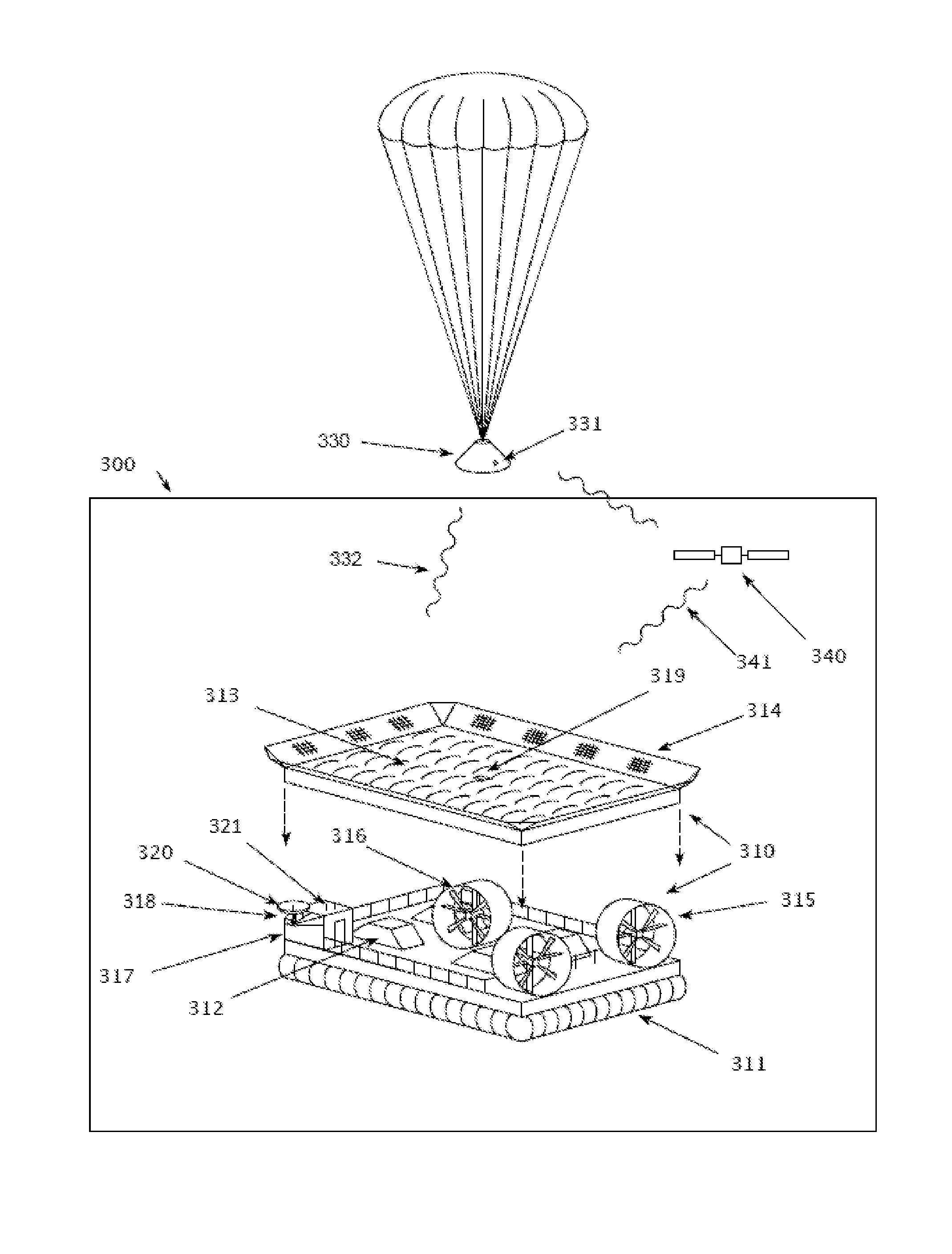
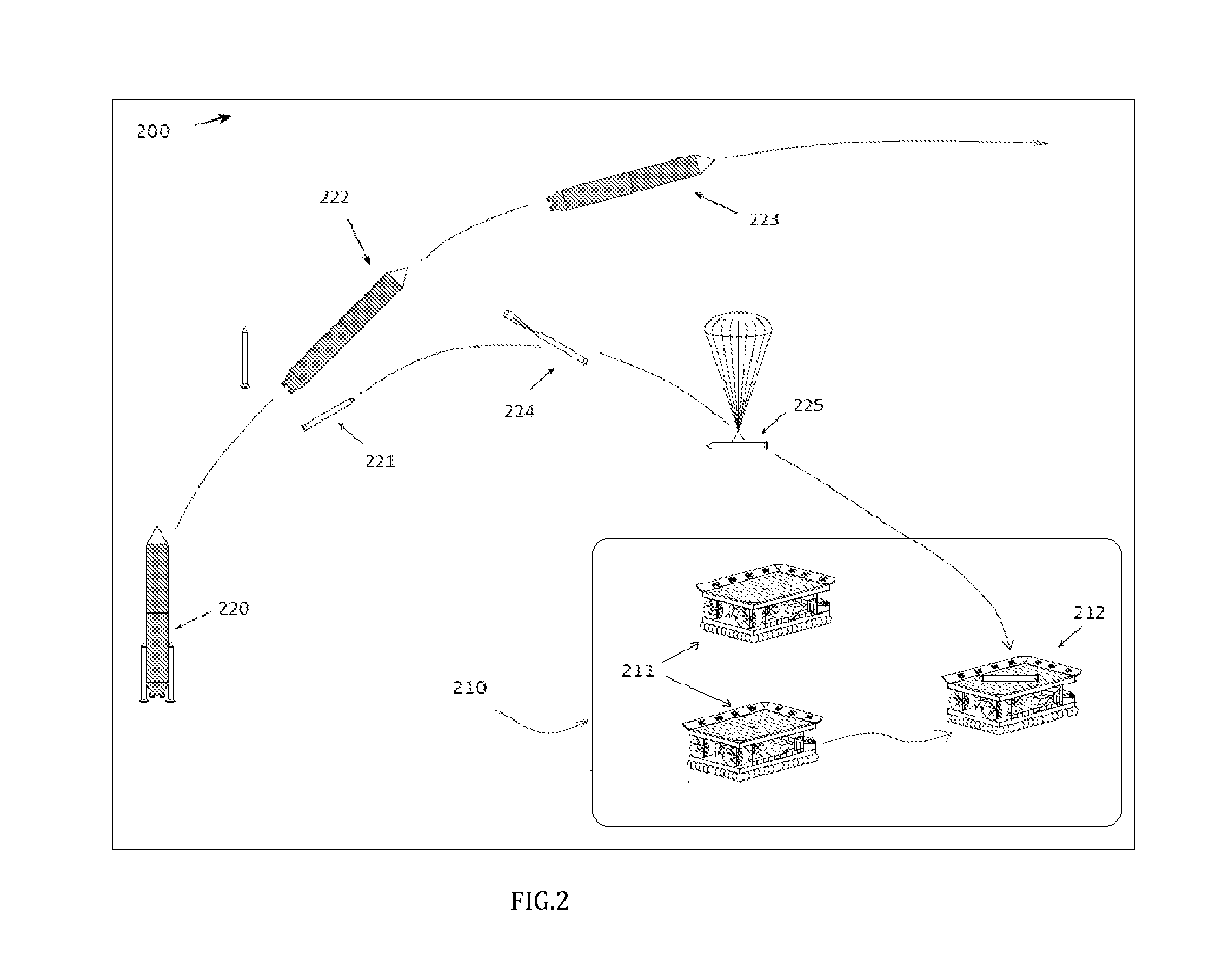
The invention is a method to capture reusable space flight hardware that passes through an atmosphere in an approach to a terrestrial surface. Ground based vehicles are pre-positioned in the landing region and the space flight hardware has an atmospheric deceleration system that allows it to descent in reaction to aerodynamic and gravitational forces. The trajectory of the space flight hardware is estimated and the ground based vehicle is maneuvered to capture it using the measured positions and the estimated trajectory. The invention also includes a hovercraft for recovery guidance, navigation, and control. The home position of the hovercraft is in the landing region and it has a surface effect levitation system comprising flexible skirts and a pressurization mechanism to mechanically capture the space flight hardware. The propulsion system of the hovercraft allows it to maneuver independently in forward / aft translation, left / right translation, and directional rotation. The guidance, navigation, and control hardware directs the motion of thehovercraft to match the speed and direction of the space flight hardware when it is captured.

Problems solved by technology

For a fixed size launch vehicle, with a small payload fraction, even a small percentage point increase in fixed weight among the heavier booster elements will radically reduce the launch vehicle's payload capacity.
For a conceptual launch vehicle, flying a design payload along an equivalent trajectory, these weight penalties of reusable systems will increase the gross-lift-off-weight in a multiplicative, rather than additive fashion.
Typical reusable technologies to enable a precision landing system (lifting bodies or wings) weigh considerably more than reusable technologies that lack precision landing capability (parachutes).
A water landing, resulting in salt-water immersion of space flight hardware, is detrimental to the reusability of complex space flight hardware.
For example, all electronics, having been exposed to the corrosive salt-water environment, must be replaced at considerable expense.
In the former, the flight hardware is immersed in salt water making the design of a reusable spacecraft much more complex and heavy.
In air capture, the relative size of an aircraft or helicopter to the returning flight vehicle limits its use to small capsules.
This technique also is not compatible with large flight vehicles due to the potential of failed capture causing the loss of the parachute and uncontrolled descent into the ground.
In these systems, the rockets or air bags add significant weight to the flight hardware and typically do not compensate for any lateral motion at landing causing significant side loads and a possibility of roll over at landing.
This leads to increased structural mass of the vehicle.
Airborne recovery of spacecraft is a hazardous operation and is not suitable for manned flight vehicles.
Air capture of a returning spacecraft can cause the loss of the parachute system in a failed capture event; the spacecraft would then fall to ground at a high velocity.
While this patent describes a vehicle that is in motion at the time of capture, the wheeled has only limited steering capability.

Method used


Image

  • Movable ground based recovery system for reuseable space flight hardware
  • Movable ground based recovery system for reuseable space flight hardware
  • Movable ground based recovery system for reuseable space flight hardware

Examples


Embodiment Construction

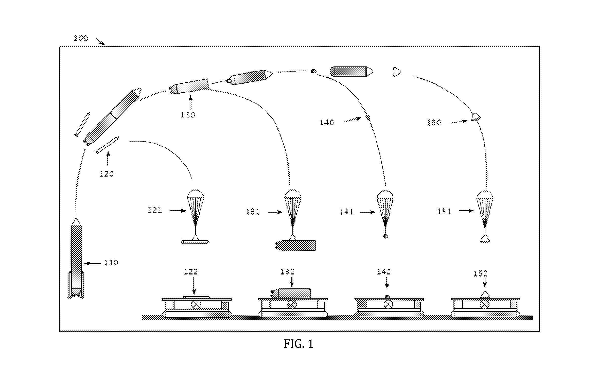
[0031]FIG. 1 shows a reusable space launch vehicle system 100 where significant elements of the launch vehicle 110 and spacecraft 150 are reusable. The reusable launch vehicle may comprise a fully reusable solid rocket booster 120, a fully reusable liquid rocket booster 130, or a partially reusable liquid rocket booster featuring a jettisonable engine pod 140.

[0032]In order to reduce the complexity of each reusable space flight hardware element, their respective recovery system will omit elements of guidance, navigation and control (GN&C) capability used for precision landing. Because any increase in the empty weight of a rocket launch system materially diminishes from its payload capability, a simple, lightweight landing parachute system to a heavier aerodynamic (wings) or propulsion (retro-rocket) based approach. Every electromechanical component required for active recovery guidance, navigation and control (GN&C) requires power. Electronics, batteries and actuators displace volum...


PUM


Abstract

A reusable space flight launch system is configured to eliminate complex descent and landing systems from the space flight hardware and move them to maneuverable ground based systems. Precision landing of the reusable space flight hardware is enabled using a simple, light weight aerodynamic device on board the flight hardware such as a parachute, and one or more translating ground based vehicles such as a hovercraft that include active speed, orientation and directional control. The ground based vehicle maneuvers itself into position beneath the descending flight hardware, matching its speed and direction and captures the flight hardware. The ground based vehicle will contain propulsion, command and GN&C functionality as well as space flight hardware landing cushioning and retaining hardware. The ground based vehicle propulsion system enables longitudinal and transverse maneuverability independent of its physical heading.

Description

ORIGIN OF THE INVENTION[0001]This invention was made, in part, by one or more employees of the U.S. government. The U.S. government has the right to make, use and / sell the invention described herein without payment of compensation, including but not limited to payment of royalties.TECHNICAL FIELD OF INVENTION[0002]An aspect of this invention relates generally to a low-cost reusable space launch system, and more particularly to a system featuring a distributed approach to configure key elements of the landing system, including guidance, navigation and control, where an actively controlled ground vehicle is used in an innovative manner to recover flight hardware such as a spacecraft or launch booster.BACKGROUND OF INVENTION[0003]In theory, a design incorporating a reusable spacecraft or booster can significantly reduce the cost of access to space. In order to realize these theoretical benefits, the launch vehicle must satisfy two design elements: 1) substantial elements of the launch ...

Claims


Application Information

Patent Timeline
Patent Type & Authority Patents(United States)
IPC IPC(8): G05D1/00G06F7/00G05D3/00G06F17/00
CPCB64G1/62B64G1/14B64G1/625B64G1/623
Inventor SARVER, GEORGE L.
Owner NASA
Learn More