
Power supply architecture for controlling and monitoring isolated output modules

a power supply and output module technology, applied in the direction of electric variable regulation, process and machine control, instruments, etc., can solve the problems of introducing undesirable complexity and size to the overall power system, prohibitive power distribution losses, etc., and achieve the effect of simplifying digital control and monitoring

Active Publication Date: 2013-08-06
BEL POWER SOLUTIONS INC
View PDF9 Cites 25 Cited by
  • Summary
  • Abstract
  • Description
  • Claims
  • Application Information

AI Technical Summary

Benefits of technology

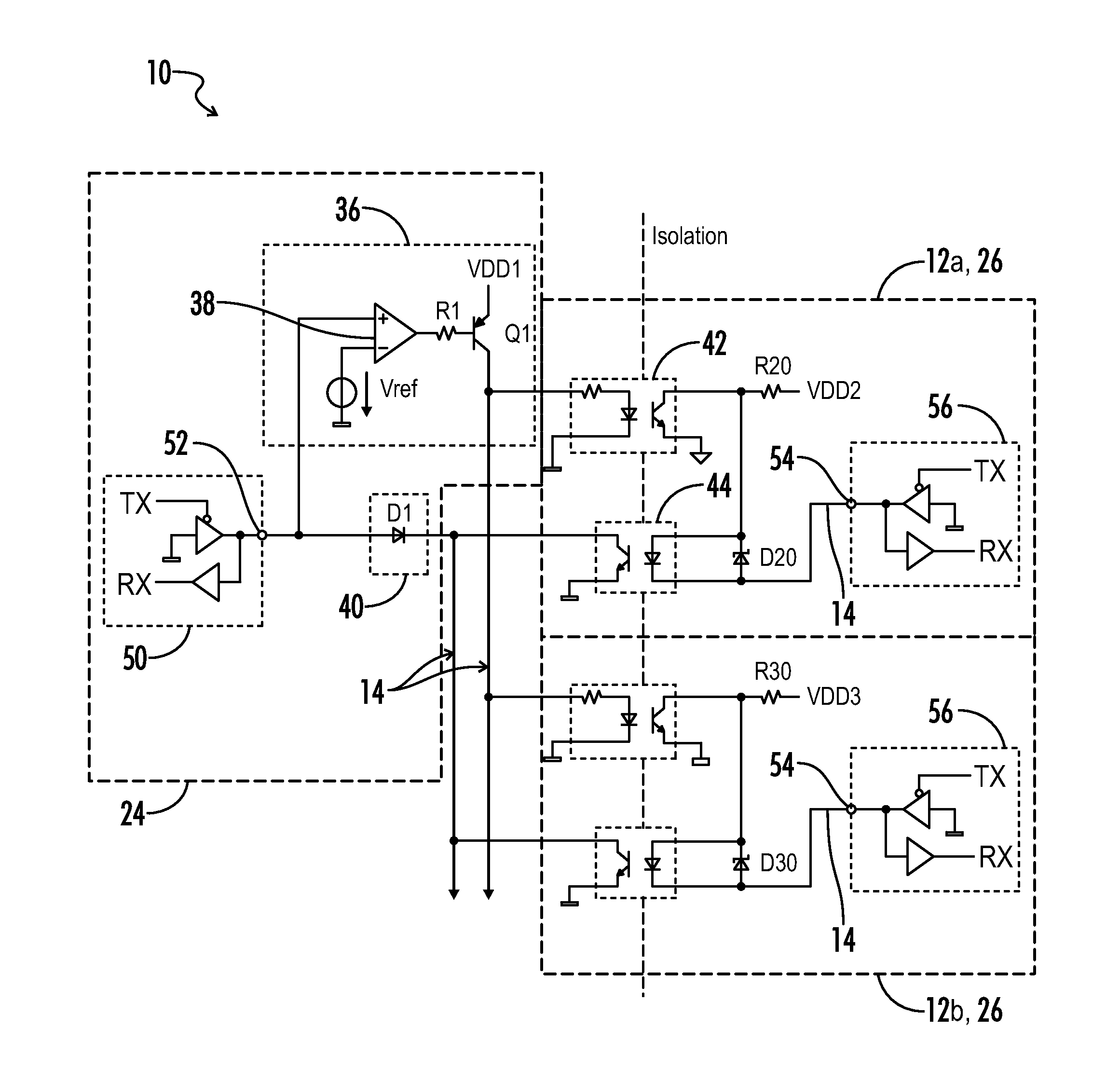
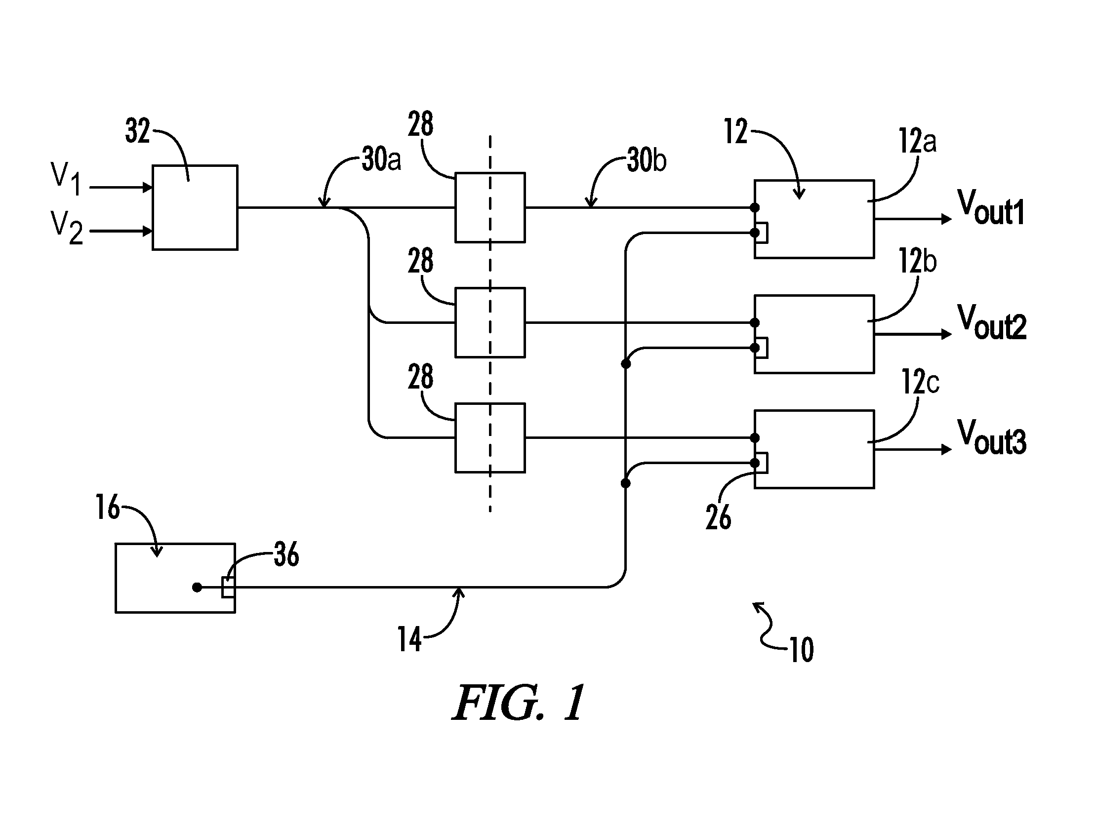
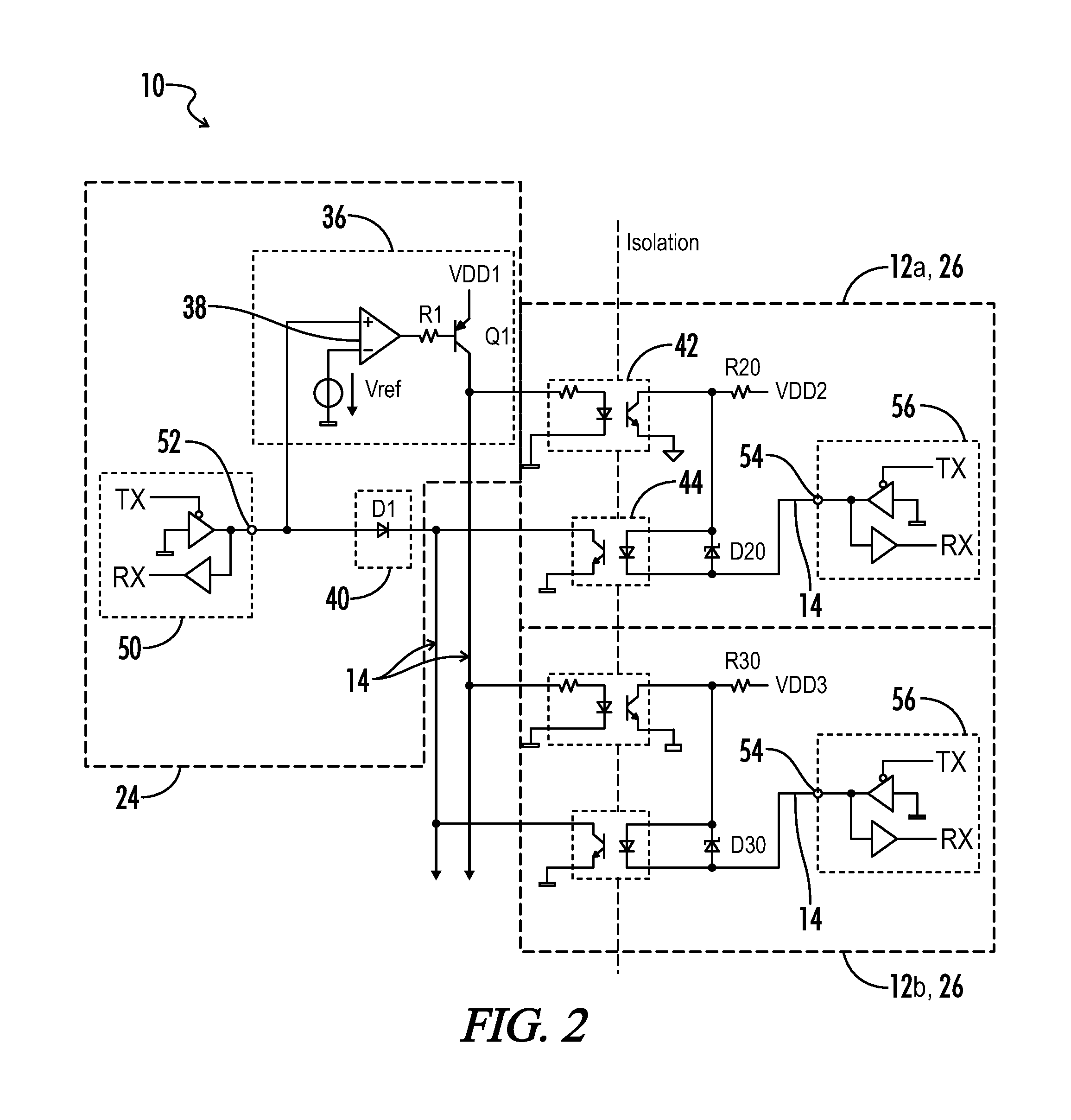
The present invention provides power supply systems and methods for easily controlling and monitoring multiple output modules. The system includes an open loop half-bridge power converter, isolation transformers, and power output modules. A digital power manager controls each output module through a serial data bus, and isolation circuits ensure that the bus remains high-level when an output module is in a low-level state. The technical effect of this invention is that it simplifies the process of controlling multiple output modules while ensuring the stability and reliability of the power system.

Problems solved by technology

It is generally considered undesirable to deliver relatively high current at low voltages over a relatively long distance through an electronic device, as power distribution losses may become prohibitive.
Such control systems often however introduce undesirable complexity and size to the overall power system.
Further, most conventional point-of-load power conversion systems provide non-isolated POL regulators, predominantly due to their lower cost.
However, non-isolated POL regulators may expose loads which are particularly sensitive to over-voltage conditions, and ground loop conditions are also a potential problem for the power system as a whole.

Method used


Image

  • Power supply architecture for controlling and monitoring isolated output modules
  • Power supply architecture for controlling and monitoring isolated output modules
  • Power supply architecture for controlling and monitoring isolated output modules

Examples


Embodiment Construction

[0037]Throughout the specification and claims, the following terms take at least the meanings explicitly associated herein, unless the context dictates otherwise. The meanings identified below do not necessarily limit the terms, but merely provide illustrative examples for the terms. The meaning of “a,”“an,” and “the” may include plural references, and the meaning of “in” may include “in” and “on.” The phrase “in one embodiment,” as used herein does not necessarily refer to the same embodiment, although it may.

[0038]The term “coupled” means at least either a direct electrical connection between the connected items or an indirect connection through one or more passive or active intermediary devices.

[0039]The term “circuit” means at least either a single component or a multiplicity of components, either active and / or passive, that are coupled together to provide a desired function.

[0040]The term “isolation circuit” as used herein may unless otherwise stated generally refer to at least...


PUM


Abstract

A modular power supply and power control system includes a digital controller coupled to each of a plurality of output modules via a single wire serial data bus having a default high logic state. A plurality of isolation transformers are each coupled on a primary side to receive an intermediate bus voltage, and further coupled on a secondary side to one of the output modules. Galvanic isolation circuits provide galvanic isolation on the serial data bus between each of the output modules and the digital controller. The digital controller further includes circuitry effective to pull a bus logic state from high to low for generating data transmission to the plurality of isolated modules. Each of the plurality of isolated modules further include circuitry effective to independently pull the bus logic state from high to low for generating data transmission to the digital controller.

Description

CROSS-REFERENCES TO RELATED APPLICATIONS[0001]This application claims benefit of the following patent application(s) which is / are hereby incorporated by reference: U.S. Provisional Application No. 61 / 252,067, filed on Oct. 15, 2009.[0002]A portion of the disclosure of this patent document contains material that is subject to copyright protection. The copyright owner has no objection to the reproduction of the patent document or the patent disclosure, as it appears in the U.S. Patent and Trademark Office patent file or records, but otherwise reserves all copyright rights whatsoever.BACKGROUND OF THE INVENTION[0003]The present invention relates generally to switch mode power control systems. More particularly, the present invention relates to a power supply architecture for controlling and monitoring a plurality of independent and isolated output modules such as point-of-load regulators.[0004]Point-of-load power conversion systems have become increasingly popular for use in contempora...

Claims


Application Information

Patent Timeline
Patent Type & Authority Patents(United States)
IPC IPC(8): G05F3/06
CPCH02M3/33592H02M3/33561Y02B70/1475H02M2001/0003H02M1/0003Y02B70/10
Inventor MOGILEVSKI, IGOR
Owner BEL POWER SOLUTIONS INC
Learn More