Eureka AIR delivers breakthrough ideas for toughest innovation challenges, trusted by R&D personnel around the world.

Indoor localization based on ultrasound sensors

Active Publication Date: 2013-08-06
BENTLEY SYST INC
View PDF5 Cites 36 Cited by
  • Summary
  • Abstract
  • Description
  • Claims
  • Application Information

AI Technical Summary

Benefits of technology

The patent describes a new way to find people inside buildings using a combination of sensors and a model of the building. The technique uses data from an inertial motion unit, a range finding device, and a structure model to determine the user's position. Particle filtering is used to eliminate particles that don't make sense, and the technique is repeated as the user moves to get a more accurate position. This technique results in a more accurate and compact map of the building, which can be used for navigation and other applications.

Problems solved by technology

Errors in the determination of this position may lead to incorrect graphics and / or text being overlaid at incorrect locations, and may substantially reduce the benefits of an AR view.
Should a first responder become disoriented, they may be unable to assist others, and may require assistance themselves, compounding the emergency situation.
Even a small error in position may disorient and endanger a first responder.
For example, should the error falsely indicate the first responder is on one side of a wall, in a space that has a route to a nearby exit, when they truly are on the other side of the wall, and thus cut off from the exit, a first responder may become trapped.
While such prepared tracking environment systems may provide reasonable position accuracy, the need to pre-position devices renders them impractical for many applications.
For instance, they may be unsuited for use with many AR applications, as the time needed to pre-position the devices may negate the potential time savings achieved by providing an AR view.
Similarly, they may be unsuited for use with guiding a user, for example, a first responder in an emergency situation, due to the time and care needed to pre-position the devices.
While this addresses some of the issues of prepared tracking environment systems, existing unprepared tracking environment systems have their own host of problems and shortcomings.
While in ideal situations, such image-based techniques may function, they are hindered by a number of practical issues.
Given similarities between different portions of the structure (e.g., each level of a multi-level structure may have an identical floor plan and thus may “look alike”) the captured image data may be insufficient to unambiguously determine the user's position.
Further, considerable processing power it typically needed to analyze and process the image data.
Still further, image-based techniques are typically inoperative in situations where visibility is impaired inside of the structure (for example, due to smoke, darkness, etc.), and therefore are unsuitable for emergency-response guidance systems.
While in theory, this is all that should be needed to determine the position of the user, in practice there are a number of issues that render such simple techniques unworkable.
However, while such technique may reduce the problem of accelerometer drift somewhat, the precision of the calculated position is still inadequate for many applications.
Yet, while such a technique may offer improved precision, even this improved precision may be inadequate for many applications.
When there are few, or no, physical constraints nearby the user, particles cannot be effectively eliminated.
For instance, a user who is moving though a large open area (e.g., a large room) within a structure may be free to move in any direction without encountering any physical constraint (e.g., hitting a wall), and because of this, the number of participles in a cloud of particles that represents their potential position may not readily be reduced.

Method used


Image

  • Indoor localization based on ultrasound sensors
  • Indoor localization based on ultrasound sensors
  • Indoor localization based on ultrasound sensors

Examples


example embodiments

II. Example Embodiments

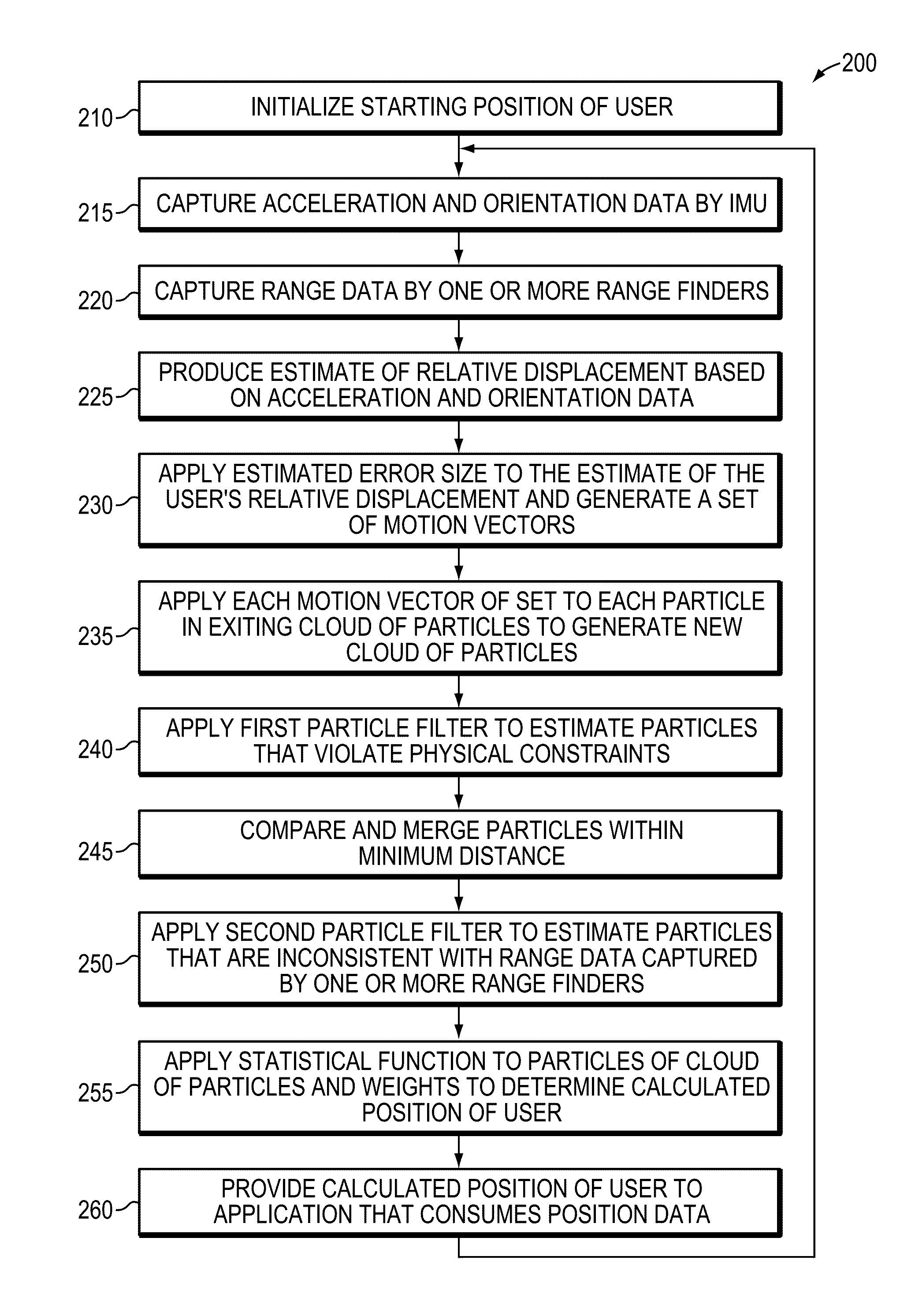
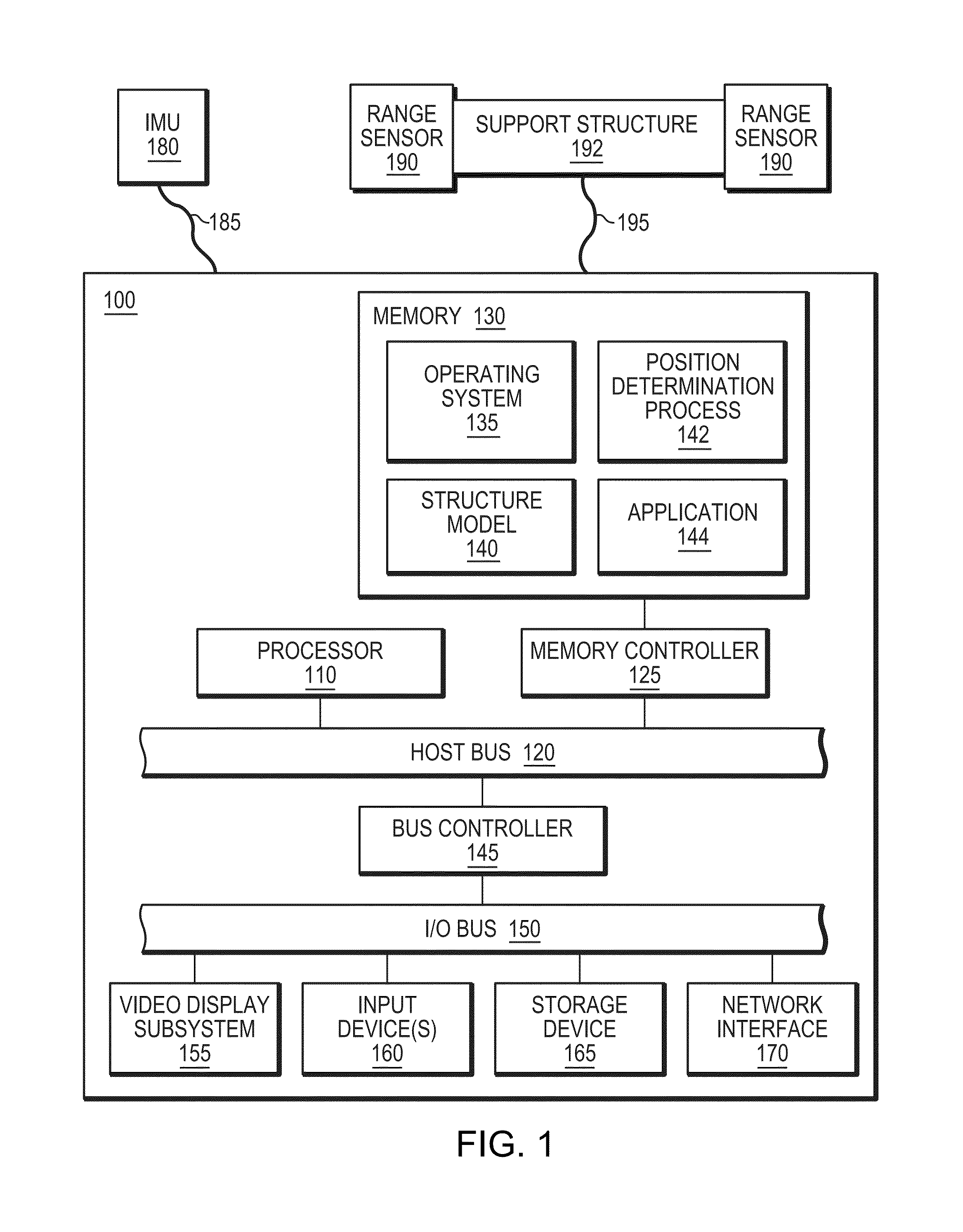
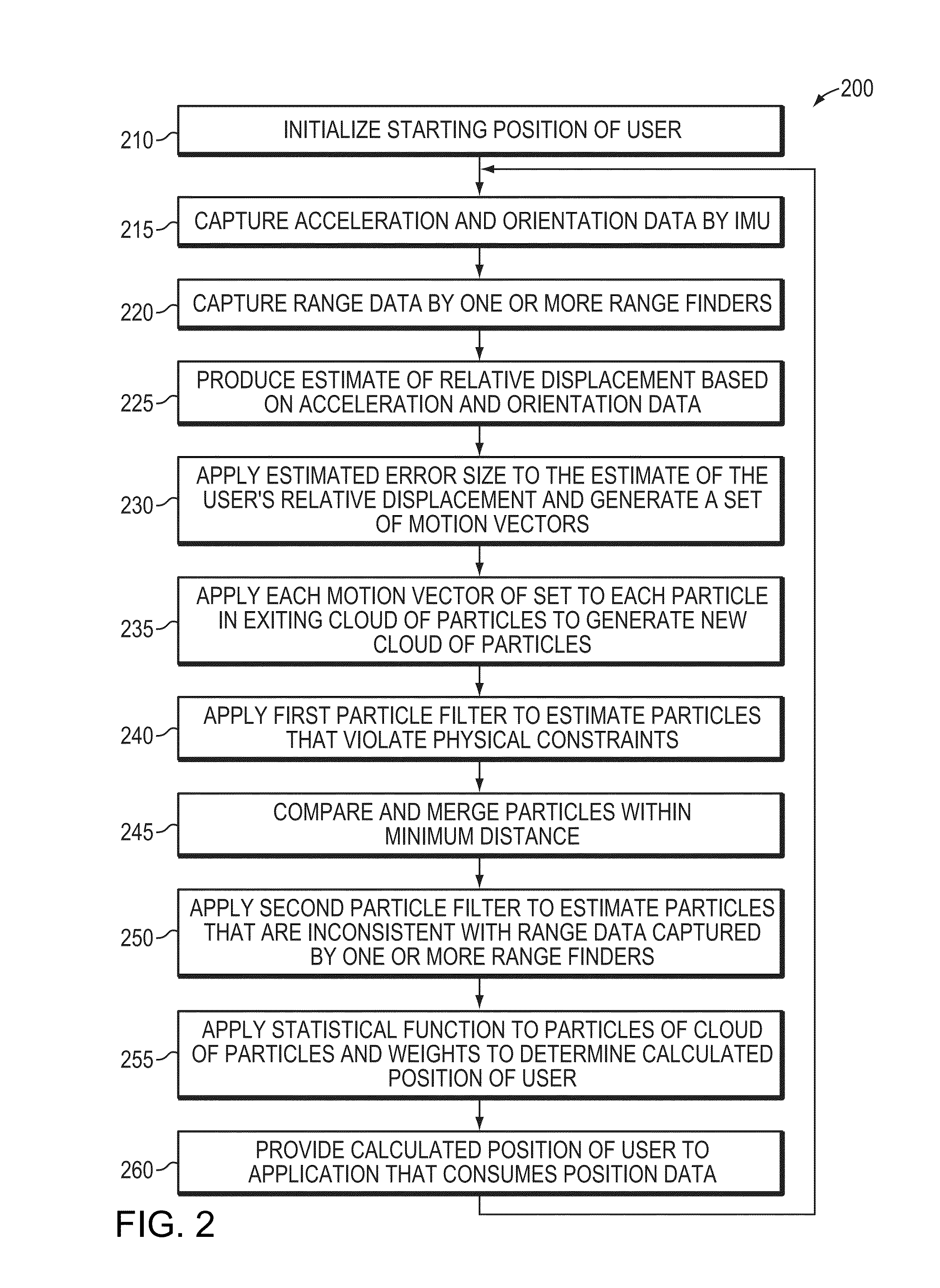
[0031]FIG. 1 is a schematic block diagram of an example portable electronic device 100 carried by a user in which at least some of the presently described techniques may be employed. The portable electronic device 100 includes at least one processor 110 coupled to a host bus 120. The processor 110 may be any of a variety of commercially available processors, such as an Intel x86 processor, or another type of processor. A volatile memory 130, such as a Random Access Memory (RAM), is coupled to the host bus 120 via a memory controller 125. The memory 130 is adapted to store at least a portion of computer-executable instructions and data for an operating system 135 while the portable electronic device 100 is operating. In addition, the memory 130 may store at least portions of computer-executable instructions and data for a structure model 140, a position determination process 142 and an application 144 that consumes position data. The structure model 140 may be ...


PUM


Abstract

In one embodiment, a technique for determining a position of a user inside of a structure is disclosed. Acceleration and orientation data is captured by an inertial motion unit (IMU) affixed to the user. Range data is captured by one or more range finders affixed to the user. An estimate of the user's relative displacement is produced based on the acceleration and orientation data captured by the IMU. A cloud of particles is generated within a model of the structure based on the estimated relative displacement. One or more particle filters are applied to the cloud of particles to eliminate any particles of the cloud of particles that violate physical constraints and to eliminate any particles of the cloud of particles that are inconsistent with the range data. Then a statistical function is applied to the cloud of particles to determine a calculated position of the user.

Description

BACKGROUND[0001]1. Technical Field[0002]The present disclosure relates generally to position determination, and more specifically to techniques for precisely determining a user's position inside of a structure.[0003]2. Background Information[0004]A variety of classes of applications may require precise determination of a user's position inside of a structure (e.g., a building). One class of applications that may require a precise fix of a user's position inside of a structure is augmented reality (AR) applications. In an example AR application, a portable system may capture images of the structure and supplement them to provide an AR view, where computer-generated graphics and / or text are overlaid upon the captured images. Such graphics and / or text may describe, among other things, features that are normally hidden from view inside the structure, such as pipes, ventilation ducts, wiring, and / or other infrastructure, and provide information concerning their properties and requirement...

Claims


Application Information

Patent Timeline
IPC IPC(8): G01C21/10
CPCG01S15/025G01S15/66G01S15/87G01C21/165G01C21/206G01S17/023G01S17/66G01S17/87G01S17/86G01S15/86G01C21/1652
Inventor COTE, STEPHANEGIRARD, GABRIELZLATANOVA, SISIBARRETTE, YANNICKVAN OOSTEROM, PETERST-PIERRE, JOHANNE
Owner BENTLEY SYST INC
Why Eureka
Eureka Blog
Learn More