Laser projector having safety lens for audience scanning

a technology of audience scanning and laser projector, which is applied in the field of laser projectors, can solve the problems of scanning failure, retinal damage, and retinal damage, and achieve the effects of increasing safety, reducing the risk of damage, and increasing the diameter

Active Publication Date: 2013-08-13
BENNER JR WILLIAM R +1
View PDF16 Cites 1 Cited by
  • Summary
  • Abstract
  • Description
  • Claims
  • Application Information

AI Technical Summary

Benefits of technology

[0020]The present invention overcomes the drawbacks of prior art projectors by allowing the projection of laser beams with a small diameter and low divergence above the heads of the audience to aid in mirror targeting applications, while allowing the projection of laser beams with larger diameter and higher divergence within the audience, thus increasing safety.
[0023]Certain embodiments of the present invention also increase the safety of the laser projector by making it such that if the safety lens is removed, the laser projector will project high divergence beams everywhere and thus, the removal of the lens becomes a fail-safe arrangement, and also an arrangement which removes the motivation of rogue club operators and DJs to remove the external lens.

Problems solved by technology

If an intense laser beam were to stop scanning and directed on the pupil of a viewer's eye, retinal damage can occur if the beam has sufficiently high power and a sufficiently long dwell time.
Likewise, even if the beam is not stopped but is scanned across the pupil of an eye, it can still cause retinal damage if the beam power is high enough, or if the beam is scanning slowly enough.
If the beam were to stop scanning, producing zero velocity, or if the velocity were to otherwise drop below some preset threshold, this would be considered a “scanning failure.” Under a scanning failure condition, the beam may be completely turned off by the light beam modulator or by a shutter.
While scan-fail monitors provide some level of protection for the audience, there are a number of problems that still remain.
First, a scan-fail monitor does not provide automatic power level control in different regions of the scan field.
For example, scan fail monitors are not capable of allowing a higher power level over the audience's heads or below their eyes.
Second, scan-fail monitors can be easily “fooled” into believing that there is a safe condition when there is not, because they only monitor the rate of change of position and do not track the actual position of the beam.
However, in many instances, a 50% concentration of beam power could be hazardous.
Because the laser beam diameter is typically small in the audience, it means that no greater than around 5 milliwatts of laser power can be used to create the laser display, regardless of the sophistication of the scan-fail monitor.
If a higher power is used, the display will not be able to meet Class 1 standards for laser safety.
When the beam is greater than 7 millimeters, it means that the entire beam will no longer fit through the pupil of a viewer's eye and thus, not all of the laser beam power will be delivered to the retina if the laser beam does land on someone's eye.
However, this approach is not without problems: Placing a lens with negative optical power before or after the scanners will decrease the divergence in all parts of the scan field, including above the heads of audience members.
The larger beam diameter caused by the lens makes such beam targeting virtually impossible.
Another drawback is that, as the beam diameter is increased, the projected effect looks more cloudy and foggy, whereas the raw beam projected from the laser makes it look as though the light is cutting through the air like a knife.
However, an external mounting arrangement can also be tampered with.
However, as noted above, low divergence beams projected into the audience would be potentially hazardous, especially if the power of the laser is greater than 5 milliwatts.

Method used


Image

  • Laser projector having safety lens for audience scanning
  • Laser projector having safety lens for audience scanning
  • Laser projector having safety lens for audience scanning

Examples


embodiment 11

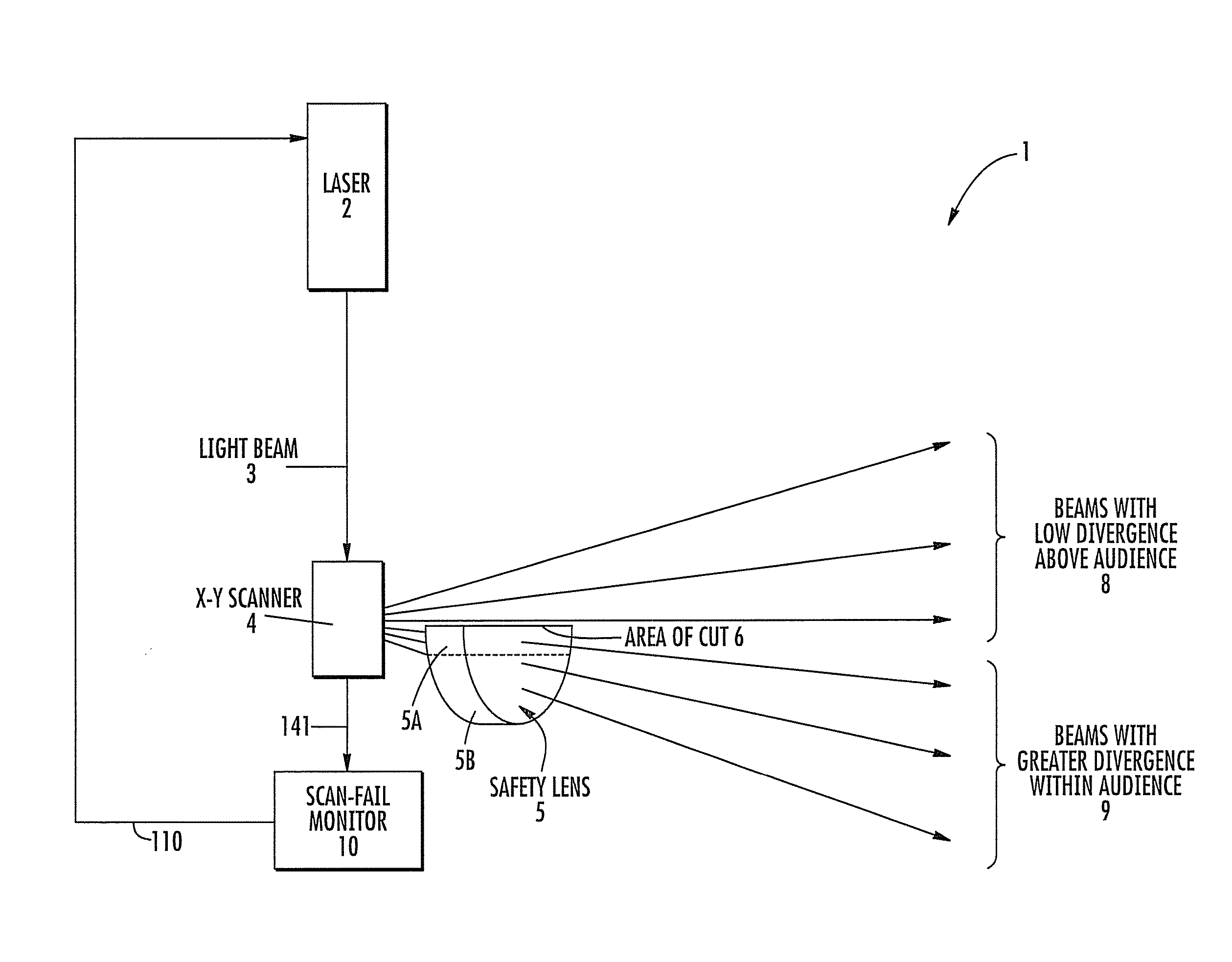
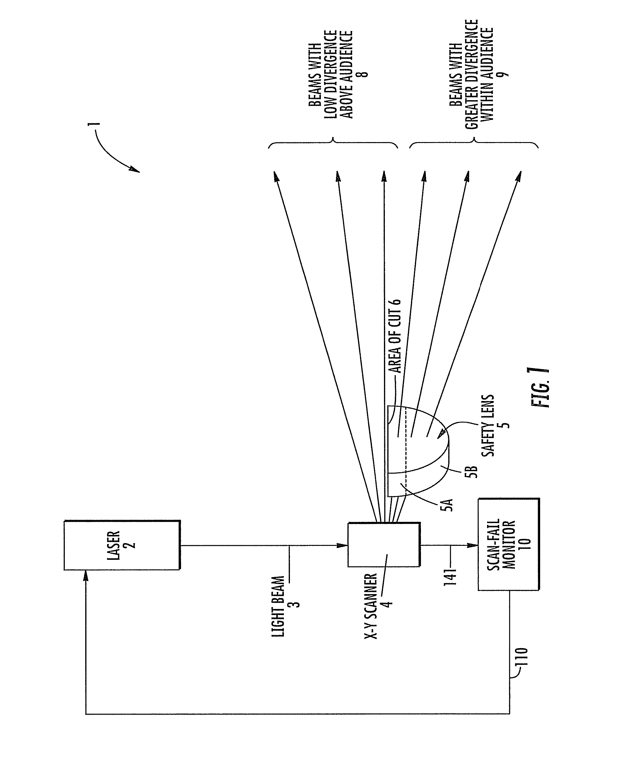
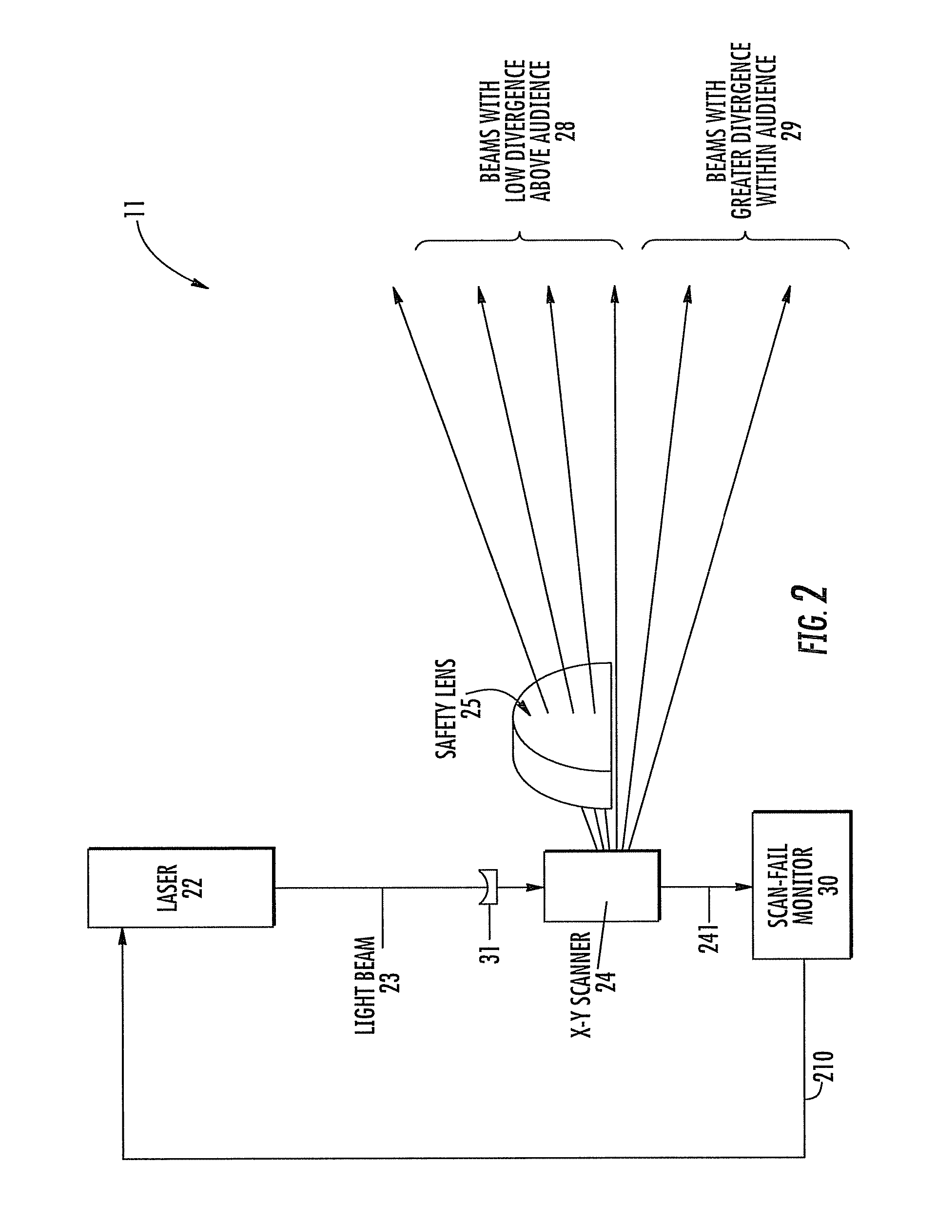
[0050]Up-collimators that comprise two lenses are known in the art, and are typically placed before the scanner. However, placing the single lens 31 before the scanner 24 and a second lens (the safety lens 25) after the scanner 24 provides a dual benefit. In this embodiment 11, the moving mirror on the scanner 24 does not have to be as big as would be the case with prior art up-collimator methods, and another benefit is provided by the fact that the safety lens 25 does not affect beams projected around where the audience resides 29.

[0051]Since the safety lens 25 is positioned in such a way as to only affect beams projected generally above the audience 28, the system will provide beams with higher divergence into the audience 29 because of the optical power of the lens 31.

[0052]Since it may be desirable for the safety lens 25 to be located externally to the projector and easily removable so that different optical powers may be used for different venues, it should be understood that t...

second embodiment

[0053]As noted above, within this second embodiment, illustrated with reference to FIG. 2 for the system 11, it is preferable to have the lens 31 configured to provide a negative optical power, and the safety lens 25 configured to have a positive optical power. However, it is possible for lens 31 to provide a positive optical power, and also possible to configure the safety lens 25 to provide negative optical power. Many lens and optical configurations are possible and still remain within the scope of this invention as long as the system places beams with lower divergence above the heads of the audience 28, and beams with greater divergence within the audience 29.

[0054]The safety lens 25 may additionally be coated with a multi-layer, reflection free coating optimized for transmittance in the visible wavelengths.

[0055]Embodiments of the present invention may be driven by a computer or other pattern generator, not shown in FIG. 1 or 2 because such is common and well known in the art.

[...


PUM


Abstract

A laser light projector includes a laser beam generated by a laser light source, a scanner associated with the laser light source and having one or more moving mirrors capable of scanning the laser beam along X-Y coordinates, a scan-fail monitor and a safety-lens. The safety-lens includes at least one optical power, and is positioned and arranged for increasing the safety of the projected light within audience areas by increasing beam divergence in the audience, while keeping beam divergence low above the heads of the audience, thus allowing mirror targeting to occur.

Description

CROSS REFERENCE TO RELATED APPLICATIONS[0001]This application is a continuation-in-part application of U.S. utility patent application Ser. No. 12 / 791,326 filed on Jun. 1, 2010 for “Laser Projector for Audience Scanning,” which itself claims priority to U.S. Provisional Patent Application Ser. No. 61 / 324,014 for “Laser Projector and Safety Lens for Audience Scanning” having filing date Apr. 14, 2010 and is a continuation-in-part application of and claims priority to U.S. Utility patent application Ser. No. 11 / 814,310 for “Laser Projector for Audience Scanning” having filing date Jul. 19, 2006 filed in a National Phase Entry from Patent Cooperation Treaty Application PCT / US2006 / 001988 having filing date Jan. 9, 2006, which itself claimed priority to Provisional Patent Application Ser. No. 60 / 645,543 filed on Jan. 19, 2005 for “Audience Scanning Laser Projector,” the disclosures of which are herein incorporated by reference in their entirety, and all commonly owned.FIELD OF THE INVENT...

Claims


Application Information

Patent Timeline
Patent Type & Authority Patents(United States)
IPC IPC(8): G03B21/00H04N9/31H04N3/28G02B26/08G02B26/10G02B17/00H04N9/10H04N3/02H01S3/10
CPCH04N9/3129
Inventor BENNER, JR., WILLIAM R.TURNER, JEREMY PHILIP
Owner BENNER JR WILLIAM R
Why Eureka
Try Eureka