Electroacoustic transducer

a transducer and electroacoustic technology, applied in the field of electroacoustic transducers, to achieve the effect of stable long-term and high efficiency

Active Publication Date: 2013-08-13
RICHARD WOLF GMBH
View PDF19 Cites 1 Cited by
  • Summary
  • Abstract
  • Description
  • Claims
  • Application Information

AI Technical Summary

Benefits of technology

[0008]Against this background, it is an object of the present invention to design an electroacoustic transducer, which is constructed of piezoelements, such that on the one hand it operates with a high efficiency, but on the other hand is stable over the long term.
[0010]The piezoelements thereby are integrated into the composite mass in a force-free manner. An adequate freedom of movement of the piezoelements, as is necessary when being subjected to voltage, is ensured by the flexibility of the composite mass.
[0014]In order to prevent functional limitations from occurring due to the electrical contacting of the piezoelements, according to a further embodiment of the invention, it is advantageous to apply as thin as possible connection wires, typically with a diameter between 0.1 mm and 0.8 mm, and to integrate these likewise into the composite mass together with the piezoelements. Such a wire thickness, with the piezoelements which are typically applied for such transducers, on the one hand permits an adequate electricity supply, and on the other hand permits a good movement ability within the elastic and flexible composite mass. In order to reduce the skin effect which occurs at higher frequencies, instead of the previously mentioned wire dimensioning, one may also use a cord of woven, fine metal wires.

Problems solved by technology

The problem of the piezoelements detaching from the carrier may no longer occur due to the fact that the piezoelements are arranged in a carrier-free manner.

Method used


Image

  • Electroacoustic transducer
  • Electroacoustic transducer
  • Electroacoustic transducer

Examples


Embodiment Construction

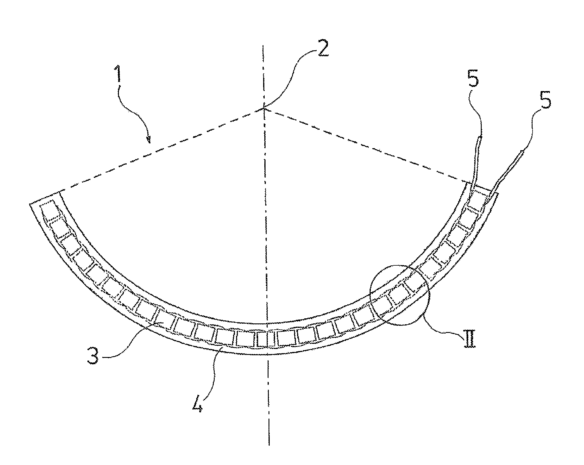
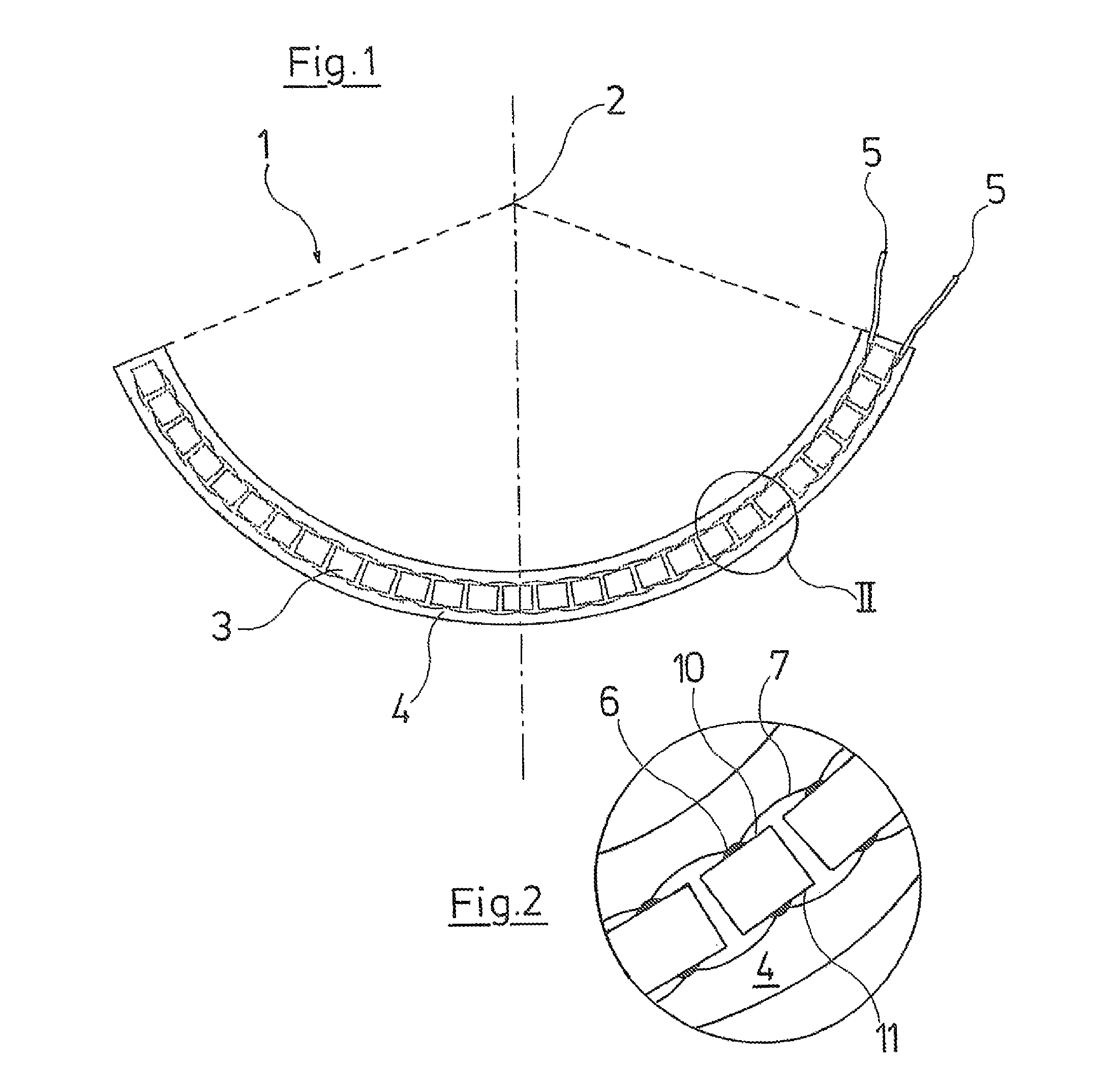
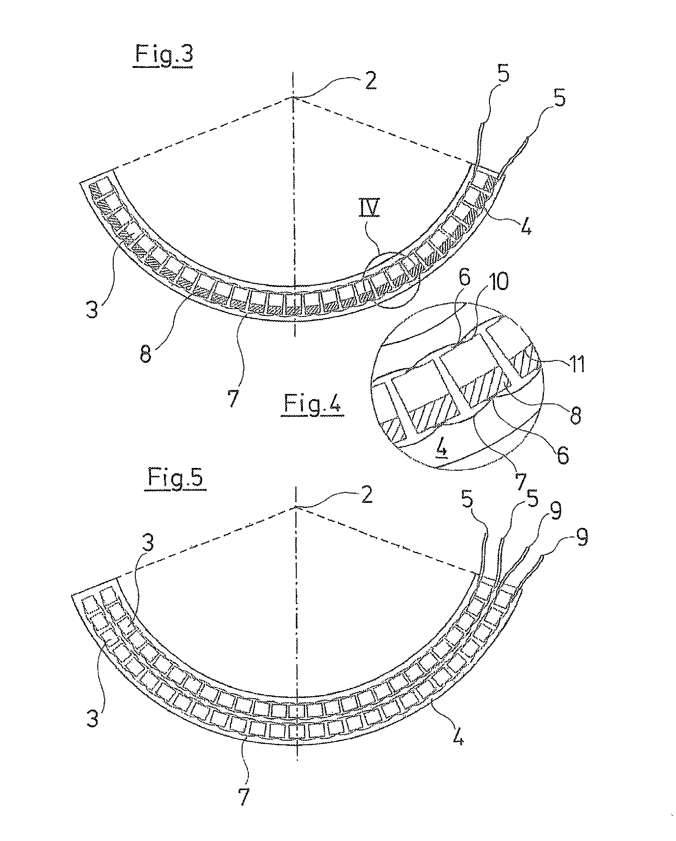
[0027]An electroacoustic transducer 1 is represented in FIG. 1, in the form of a self-focussing transducer calotte, as is often used with shock-wave treatment apparatus which operate according to the piezoelectric principle. The electroacoustic transducer 1 has a therapy focus 2, which is formed by the geometric middle point of the transducer calotte. This electroacoustic transducer 1 also comprises a multitude of piezoelements 3, which are arranged at a small spacing to one another and which are arranged in a carrier-free manner, such that they lie on an imagined hemispherical calotte. The piezoelements 3 are held by a composite mass 4 in the form of a flexible cast mass, in which the piezoelements 3 are completely embedded, which means to say they are embedded on all sides and in a force-free manner. The cast mass 4 is formed by a curing epoxy resin. On the one hand, the cast mass 4 has such a flexibility and elasticity that the piezoelements 3 which are embedded therein may suita...


PUM


Abstract

An electroacoustic transducer is provided, particularly for use in an apparatus for medical shock-wave treatment. The transducer includes several piezoelements arranged next to one another, which are embedded in a composite mass in a carrier-free manner.

Description

BACKGROUND OF THE INVENTION[0001]The invention relates to an electroacoustic transducer, in particular for use in an apparatus for medical shock-wave treatment, in which the transducer has a plurality of piezoelements arranged next to one another.[0002]Such electroacoustic transducers are part of the state of the art and are used for example in lithotripters, such as for non-invasive treatment of stone problems. Medical shock-wave treatment apparatus meanwhile are very widespread in the medical field and are also applied for numerous other therapy purposes. Various physical principles are known for the production of shock waves. The subject matter of the present invention involves those apparatus which operate according to the piezoelectric principle, which means they have an electroacoustic transducer which is constructed from a multitude of piezoelements, also referred to as piezoelectric elements.[0003]Such electroacoustic transducers are often designed as self-focussing transduc...

Claims


Application Information

Patent Timeline
Patent Type & Authority Patents(United States)
IPC IPC(8): H01L41/08A61B8/00
CPCA61B17/225
Inventor BAUER, EDGAR
Owner RICHARD WOLF GMBH
Why Eureka
Try Eureka