Controller and method of operating a controller

a controller and controller technology, applied in the direction of electric variable regulation, process and machine control, instruments, etc., can solve the problems of delay in start-up, reduce the efficiency gain to be had by switching off the current generator, etc., and achieve the effect of quick settl

Active Publication Date: 2013-08-13
NXP BV
View PDF15 Cites 31 Cited by
  • Summary
  • Abstract
  • Description
  • Claims
  • Application Information

AI Technical Summary

Benefits of technology

[0010]Preferably the off time initially is related to and may correspond to a no-load time, which no-load time is the time during which the or each pulse modulated signals are off such that the or each load is zero. Alternatively the off-time initially may correspond to the no-load time reduced by a predetermined default lead time. Provision of such a default or start up lead time may conveniently enable the controller to quickly settle.
[0011]Advantageously, in step (b) the lead-time is determined by dividing a predetermined operating current level by the rate of change of current. Thus the controller is easily able to determine a suitable lead-time.

Problems solved by technology

Although it would be possible to provide a preset ramp-up lead time, this would lead to either a reduction of the efficiency gain to be had by switching off the current generator, or some level of delayed start up.

Method used


Image

  • Controller and method of operating a controller
  • Controller and method of operating a controller
  • Controller and method of operating a controller

Examples


Embodiment Construction

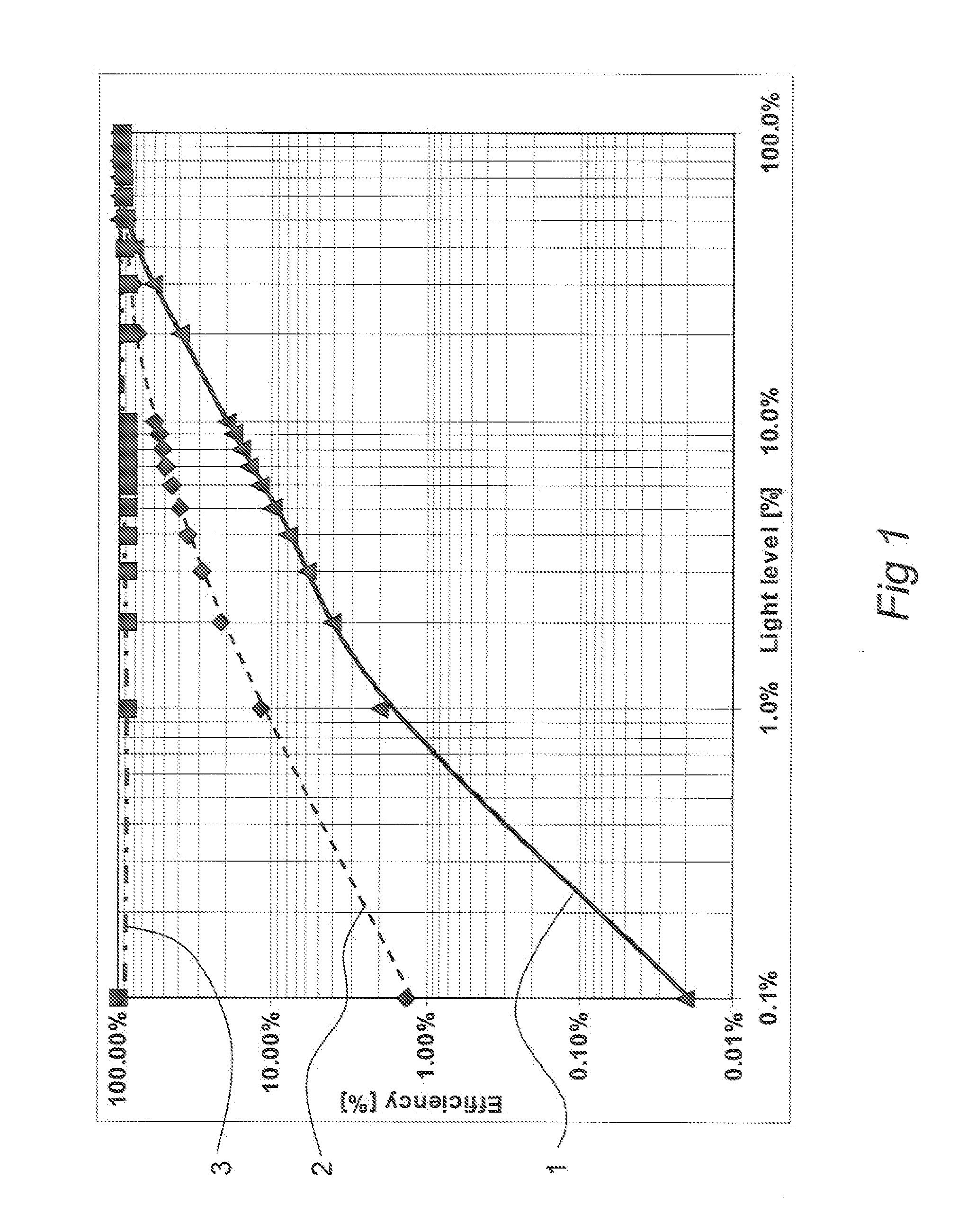
[0026]FIG. 1 illustrates the savings in efficiency which may be made by switching off a current generator during the no load periods of an LED drive circuit. The figure shows a calculation for a system in which two bypass switches are connected to a single current source. The efficiency of the system is plotted against the light level. In this example the two pulse modulated signals applied to the two bypass switches are 50% out of phase (corresponding to a worse-case situation). Curve 1 indicates the percentage of the PWM (Pulse Width Modulation) duty cycle for which the current source needs to be switched on. Curve 2 shows the efficiency of a system in which the current source is not switched off in the no-load situation; this may be compared with curve 3 which shows the efficiency of a system where the current generator is switched off when not required. From the figure it is clear that at a 1% light level turning off the converter increases the system efficiency in this example ...


PUM


Abstract

A controller for controlling a power generator circuit, and a method for operation such a controller, is disclosed. The invention is particularly suited to LED current generators. The current generator may be switched off to conserve power when not required for any LED circuits. The method relates to determining the time at which the controller is required to provide power, current or voltage, and to adjust the timing of switching-on of the controller, in order to ensure that power, current or voltage is available for the load when required.

Description

FIELD OF THE INVENTION[0001]This invention relates to a controller for controlling a power generator circuit, and a method of controlling such a controller. It has application in particular in, but not limited to, controllers for controlling LED current generators.BACKGROUND OF THE INVENTION[0002]Power supply circuits are known for multicolour LED systems wherein a single LED current generator is connected to a plurality of subsets of LEDs. The LEDs may, for example, have different colours. In order to control the brightness of the different colour LEDs, and therefore the overall appearance of the LED display, the subsets of LEDs are driven with different levels of power. This may be conveniently done by supplying each subset of LEDs with a pulse modulated signal. The pulse modulated signals are typically provided by a current generator. The current generator must be able to supply sufficient power to multiple subsets of LEDs when the pulse modulated signals have overlapping on-time...

Claims


Application Information

Patent Timeline
Patent Type & Authority Patents(United States)
IPC IPC(8): G05F1/40H05B44/00
CPCH05B37/02H05B47/10
Inventor DEURENBERG, PETER H. F.VAN DER HORN, GERT
Owner NXP BV
Why Eureka
Try Eureka