Objective lens system

a fixed focal length, objective technology, applied in the direction of optics, lenses, instruments, etc., can solve the problems of large size of zoom lenses, poor image quality, and larger size of equivalent aperture prime lenses, and achieve high relative illumination and high contrast

Active Publication Date: 2013-08-13
ERNST LEITZ WETZLAR GMBH
View PDF46 Cites 6 Cited by
  • Summary
  • Abstract
  • Description
  • Claims
  • Application Information

AI Technical Summary

Benefits of technology

[0014]The invention aims to provide an improved prime objective lens that is not only compact but also provides high relative illumination and high contrast at elevated spatial frequencies even when using a fast aperture.

Problems solved by technology

However, zoom lenses have disadvantages in that they tend to be larger in size, heavier and typically are only capable of providing poorer image quality than prime lenses of equivalent aperture.
Also, the increased optical and mechanical complexity, in terms of greater number of lens elements and moving groups, typically make zoom lenses larger in size than equivalent aperture primes lenses.
This requirement has become more difficult to satisfy because electronic detector development has led to electronic detectors with increased resolution without any reduction in contrast.
Further, in professional imaging applications as compared to consumer applications, lenses generally tend to be expensive and thus are expected to be long lived over a span of several technology cycles of detector development.
The requirement for high relative illumination makes it increasingly difficult to maintain high image quality.
However, when the off-axis beam size is large it means that the bundle of rays passing through the system corresponding to a particular off-axis image point will be spread across a larger cross-sectional area of the component lens elements and will therefore potentially be subject to greater aberrations than would be the case for a narrower bundle of rays.
Satisfying the competing requirements of high image quality, high relative illumination and constant back focal length may increase the optical and mechanical complexity to such an extent that a prime lens size becomes unacceptably large.

Method used


Image

  • Objective lens system
  • Objective lens system
  • Objective lens system

Examples


first embodiment

[0052]A preferred embodiment of the present invention will now be described by way of design examples with reference to FIGS. 7 and 8a to 8c, corresponding Table 1 and the optical prescription data contained therein which is extracted from data produced by CODEV V® optical design software that is commercially available from Optical Research Associates, Inc., Pasadena, Calif., U.S.A. All of the data contained herein is given at a temperature of 25° C. (77° F.) and standard atmospheric pressure (769 mm Hg).

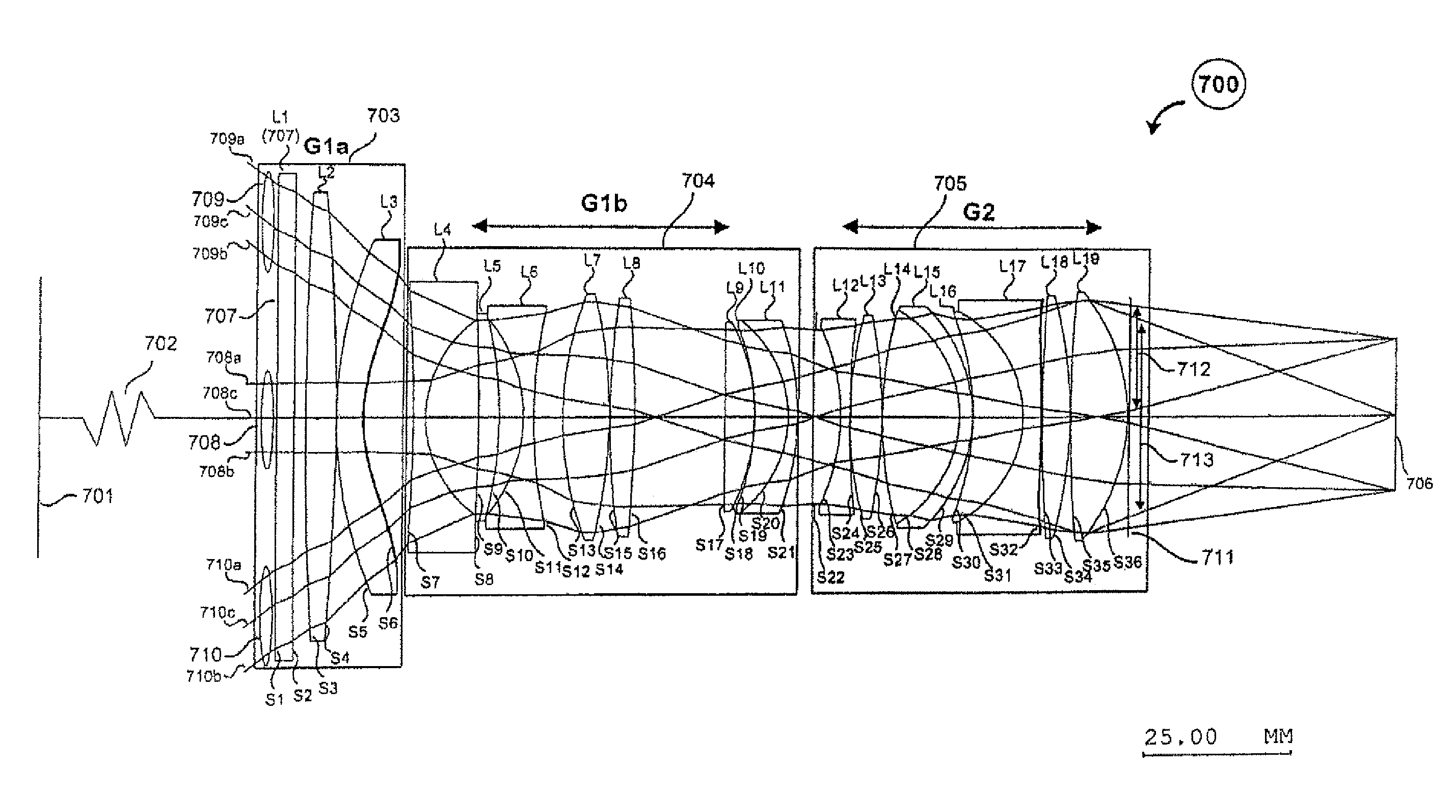
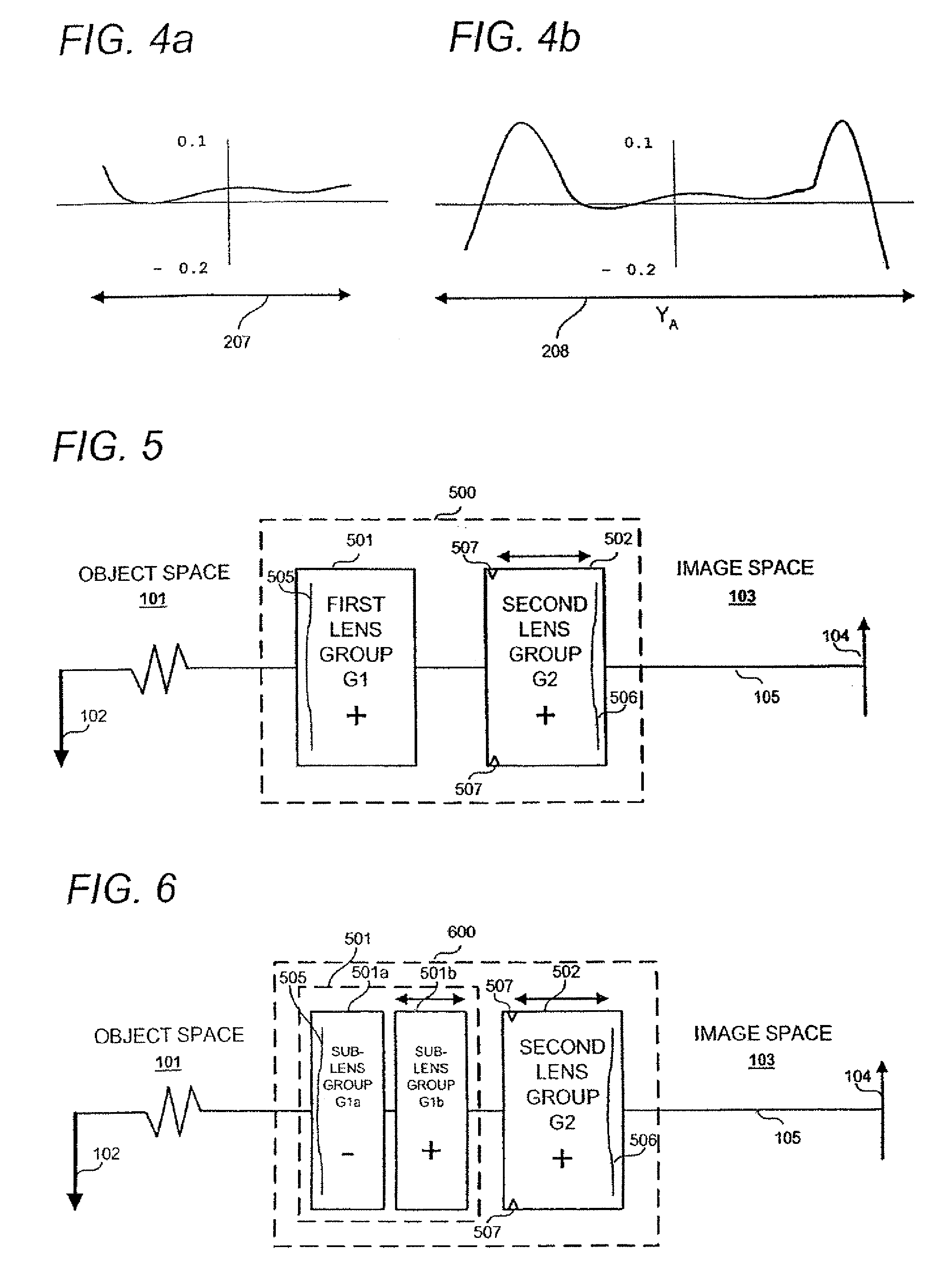
[0053]Turning now to FIG. 7, in a preferred embodiment of the present invention a wide-angle prime lens 700 with a fixed focal length of substantially 18 mm is shown that comprises a plurality of lens elements. The lens 700 is configured in accordance with the lens group power configuration 600 illustrated in FIG. 6 and already described above. Each lens element is identified by a label comprising the letter ‘L’ and a numeral ranging from 1 through 19. The shape and configuration of...

second embodiment

[0080]Turning now to FIG. 12, in a second embodiment of the present invention a medium-angle prime lens with a fixed focal length of substantially 40 mm is shown comprising a number of lens elements. The lens 1200 utilises the lens group power configuration illustrated in FIG. 5 and described above. Each lens element is again identified by a label comprising the letter ‘L’ and a numeral 1 through 16. The shape and configuration of each lens element being as depicted while the specific radius of each lens surface is given in Table 3, each surface again being identified by a label comprising the letter ‘S’ followed by a numeral. The surfaces are numbered in sequence starting at S1 for the surface nearest the object side of the lens and ending S29 for the last optical surface at the rear of the lens. While only the lens elements L 1 to L16 are shown in FIG. 11 it is to be understood that conventional mechanical devices and mechanisms are provided (but not shown) for supporting the lens...

third embodiment

[0098]Turning now to FIG. 15, in a third embodiment of the present invention 1500 a narrow-angle prime lens with a fixed focal length of substantially 100 mm is shown that comprises a plurality of lens elements. The lens 1500 is configured in accordance with the lens group configuration illustrated in FIG. 6 and described above. Each lens element is once again identified by a label comprising the letter ‘L’ and a numeral from 1 through 14. The shape and configuration of each lens element being as depicted while the specific radius of each lens surface is given in Table 5, each surface once again being identified by a label comprising the letter ‘S’ followed by a numeral. The surfaces are numbered in sequence starting at S1 for the surface nearest the object side of the lens and ending S26 for the last optical surface at the rear of the lens. As with the previous embodiments, while only the lens elements are shown in FIG. 15, it is to be again understood that conventional mechanical ...


PUM


Abstract

A high performance fixed focal length optical imaging system for example for a cine camera is operable to receive radiation from an object space and deliver the received radiation through the optical system so as to form an image at an image surface in an image space. The imaging system has the advantage of providing high relative illumination and high contrast at elevated spatial frequencies even when using a fast aperture.

Description

REFERENCE TO PRIOR FILED APPLICATIONS[0001]This application is a continuation-in-part of U.S. patent application Ser. No. 12 / 200,487 filed on Aug. 28, 2008, which is a continuation-in-part of U.S. patent application Ser. No. 12 / 197,526 filed on Aug. 25, 2008, the contents of which are hereby incorporated by reference.FIELD OF THE INVENTION[0002]This invention relates to fixed focal length objective lens systems and in particular but not exclusively to objective lens systems suitable for use with fast aperture electronic and film based cameras and operable to produce high quality images with minimal image shading.DESCRIPTION OF RELATED ART[0003]The advent of high performance electronic detectors, for the detection of radiation in video camera systems, which may be used in high performance imaging applications, has led to a demand for objective lenses that exhibit imaging characteristics and performance features which produce high quality images when used with electronic based image c...

Claims


Application Information

Patent Timeline
Patent Type & Authority Patents(United States)
IPC IPC(8): G02B3/02G02B9/06
CPCG02B13/18
Inventor NEIL, IAIN A.
Owner ERNST LEITZ WETZLAR GMBH
Why Eureka
Try Eureka