
Variable exponent averaging detector and dynamic range controller

a detector and variable exponent technology, applied in the direction of digital/coded signal control, instruments, computation using denominational number representation, etc., can solve the problems of poor separation of static and dynamic control, limited method to control the dynamic response of automatic gain control (“agc”), and little or no artistic ability, so as to improve the determination of average signal level

Active Publication Date: 2013-08-13
MASSENBURG GEORGE
View PDF10 Cites 3 Cited by
  • Summary
  • Abstract
  • Description
  • Claims
  • Application Information

AI Technical Summary

Benefits of technology

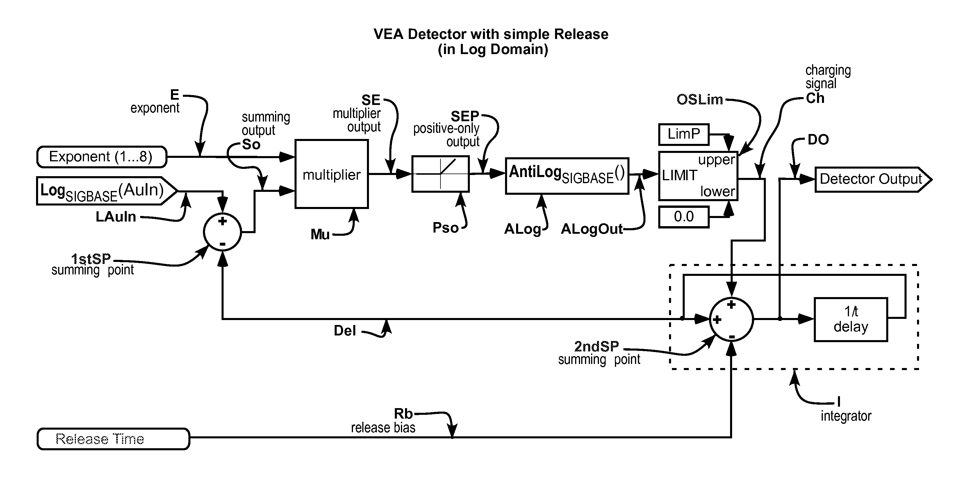
[0017]The VEA Detector improves the determination of average signal level of an audio program signal as perceived by the human ear, and determination of average signal level of a displayed video program signal as perceived by the human eye, and better uses the dynamic characteristics of a given program input signal to automatically control the dynamic range of the program signal.

Problems solved by technology

Unfortunately, methods to control the dynamic response of automatic gain controls (“AGC's”) that can be implemented using simple first-order linear filters are severely limited.
Prior art audio DRCs, AGCs, and compressors typically provide a user with the ability to prevent distortion (e.g., overmodulation) and a minimum program signal value, but provide little or no ability to artistically “shape” the program signal to produce aesthetically pleasing processing effects related to program signal dynamics or to solve problems associated with dynamic changes.
This inability arises in large part from the poor separation of static and dynamic control and the universal use of root mean square (“RMS”) detection of program signal values.
Prior art video DRCs typically provide a user with no ability to artistically “shape” the program signal to produce aesthetically pleasing effects or to solve problems associated with dynamic changes.
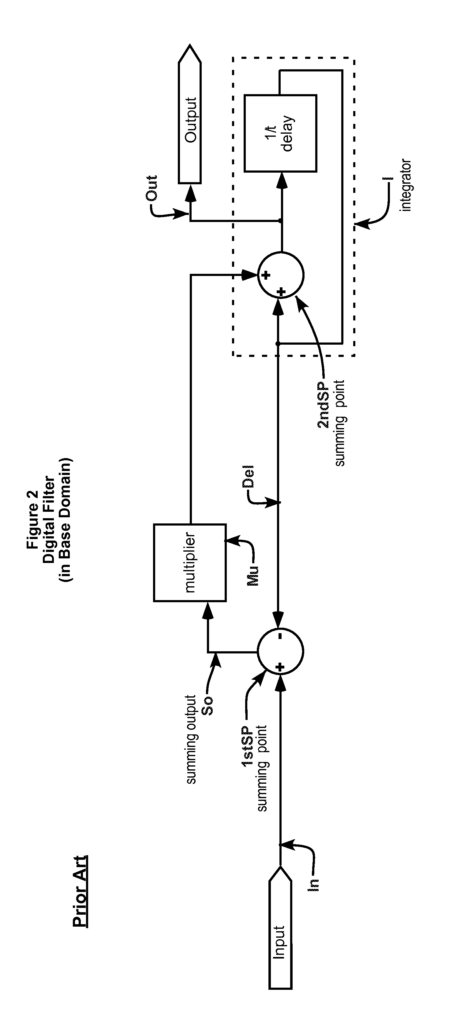
The prior art of signal detection in dynamic range controllers used various non-linear approximations to address complex waveforms and / or dynamic signals, and depended on first-order filters that provided limited or poor dynamic control over transfer functions, and failed to convey complex signal dynamics.
Although some prior art detectors and DRCs perform signal detection and processing in the log domain, the performance of such devices is not noticeably better than (i) analog devices used with analog signals, or (ii) digital processing using “native” digital signals, e.g., WAV, AIFF, AU, and PCM.

Method used


Image

  • Variable exponent averaging detector and dynamic range controller
  • Variable exponent averaging detector and dynamic range controller
  • Variable exponent averaging detector and dynamic range controller

Examples


Embodiment Construction

[0051]The Variable Exponent Averaging (“VEA”) Detector and Variable Exponent Averaging Dynamic Range Controller (“VEA DRC”) of the invention provide a means of separating control over DC, static, and dynamic action of a dynamic range controller. A “VEA Processor” has one or more VEA Detectors, and optionally includes a Control Processor. A VEA Processor always has at least one VEA Detector. If a VEA Processor has two or more VEA Detectors or Detector subsystems, then it may also have a Control Processor to prioritize or otherwise integrate or select the outputs of the two or more VEA Detectors and Detector subsystems. A VEA Processor controls a digitally controlled amplifier (“DCA”) or other digital processor (e.g., comparator, pattern discriminator, etc.). The combination of a VEA Processor and a DCA is a VEA DRC. For ease of reference, the combination of a VEA Processor and other digital processor to which a VEA Processor provides a Control Value is also called a VEA DRC, although...


PUM


Abstract

The VEA Detector and Dynamic Range Controller of the invention more accurately measure constant or non-constant, periodic or aperiodic, signals and the use of such measurements to control the upstream and / or downstream processing of program signals, including without limitation audio, video, and power program signals. The invention uses an antilog module acting within the context of a log domain circuit such that the “averaging” at an integrator is linear, not logarithmic. However, since the detection is within the log domain, the dynamic range of the VEA Detector is exponentially larger.

Description

BACKGROUND OF THE INVENTION[0001]1. Technical Field[0002]The VEA Detector and Dynamic Range Controller of the invention concern the accurate measurement of constant or non-constant, periodic or aperiodic, signals and the use of such measurements to control the upstream and / or downstream processing of program signals, including without limitation audio, video, and power signals.[0003]2. Related Art[0004]In the field of program signal processing, for example, audio signal processing, “average” or “peak” signal level detectors in prior art dynamic range controllers detect input level changes by means of non-linear or time-variant filters imposed upon the envelope of the signal. Typically, first order filters have been used. Any such filter with unity gain at DC leaves the static performance of a dynamic range controller unchanged thereby allowing the non-linear processing of that filter to control dynamic signal changes independently.[0005]Unfortunately, methods to control the dynamic ...

Claims


Application Information

Patent Timeline
Patent Type & Authority Patents(United States)
IPC IPC(8): G06F17/10
CPCH03G3/002H03G9/005H03G7/007H03G3/3089G06F7/556
Inventor MASSENBURG, GEORGE
Owner MASSENBURG GEORGE
Learn More