Wind turbine

a wind turbine and turbine blade technology, applied in the direction of wind turbines with perpendicular air flow, wind turbines with parallel air flow, etc., can solve the problems of energy loss during the process, frequent and costly repairs, etc., to reduce friction force, increase electrical power, and increase efficiency

Active Publication Date: 2013-08-20
HOVER ENERGY LLC
View PDF148 Cites 20 Cited by
  • Summary
  • Abstract
  • Description
  • Claims
  • Application Information

AI Technical Summary

Benefits of technology

[0005]The present invention increases the efficiency of a wind turbine because the friction occurring between the parts of a wind turbine is significantly reduced. The wind turbine of this invention comprise a turbine rotor, a turbine support, one or more blades coupled to the turbine rotor, the one or more blades configured to move the turbine rotor relative to the turbine support. The significant improvement in efficiency is attributed to one or more magnet sets located between the turbine support and the turbine rotor. The one or more magnet sets create a space between at least a portion of the turbine rotor and a portion of the turbine support. Alternatively, the space created by the magnet is between the entire turbine rotor and the entire turbine support. The rotational movement of the turbine rotor is essentially frictionless and minimal energy is expended during rotation of the turbine blades. The energy output produced by the turbine rotor is transmitted to one or more generators that are configured to generate electric power from the rotational movement of the turbine rotor.
[0007]In another aspect of this invention, a space is defined between at least a portion of the turbine rotor and a portion of the turbine support, wherein the space is created by the opposing forces of the one or more magnet sets. The space helps to reduce the friction between the rotating turbine rotor and the turbine support. One or more generators are configured to generate electric power in response to the movement of the turbine rotor relative to the turbine support.
[0009]The one or more generators have a generator gear; and a turbine gear, wherein the turbine gear is configured to move the generator gear. To further improve efficiency of the wind turbine, a magnetic gear connection is present between the generator gear and the turbine gear. The magnetic gear connection is configured to move the generator gear with reduced friction between the turbine gear and the generator gear. The one or more generators can comprise at least one linear synchronous generator.
[0011]In an alternative embodiment of a wind turbine, the wind turbine comprises a turbine rotor, a turbine support; and one or more blades coupled to the turbine rotor, the one or more blades configured to move the turbine rotor relative to the turbine support in response to wind engaging and rotating the one or more blades. This embodiment of the wind turbine also comprises one or more magnet sets located between the turbine support and the turbine rotor, the one or more magnets positioned on the turbine support and / or the turbine rotor to create a space between the turbine support and the turbine rotor thereby reducing friction between the turbine support and the turbine rotor. One or more generators are configured to generate electric power in response to the relative rotational movement between the turbine rotor and the turbine support frame. The turbine support frame further comprises a base located below the turbine rotor, a support shaft located along a central axis of the turbine rotor and a top configured to cover a substantial portion of the turbine rotor and the one or more blades. Advantageously, the wind turbine of this embodiment has a top that further comprises an observation deck for one or more persons to access. The support shaft has an interior access way configured to allow the one or more persons to travel to and from the observation deck. The interior access way can comprises an elevator for easy access.
[0013]In a method for generating electricity, advantageously, the method comprises lifting a vertical turbine rotor off of a turbine support using one or more sets of magnets thereby reducing the friction between the vertical turbine rotor and the turbine support. As one or more blades coupled to the vertical turbine rotor engage with wind, the vertical turbine rotor rotates relative to the turbine support and the mechanical energy of the moving vertical turbine rotor is converted into electric power using a generator. The one or more sets of magnets are used to create a space between the vertical turbine rotor and the turbine support. In this method, the turbine support further comprises a support shaft and a base, the base further comprising a platform located substantially under a bottom of the turbine rotor and the method further comprises using one or more levitation magnet sets positioned on the platform adjacent the bottom of the turbine rotor and one or more levitation magnet sets positioned on the bottom of the turbine rotor adjacent to the platform, wherein the one or more levitation magnet sets on the platform and the one or more levitation magnet sets on the bottom of the turbine rotor create an opposing force resulting in a space between the turbine rotor and the turbine support.
[0015]In an alternative method for generating electricity, a set of dipolar magnets is coupled to a turbine rotor and a turbine support. The set of dipolar magnets is used to create a space between the turbine rotor and turbine support thereby reducing the friction force between the turbine rotor and the turbine support. In this way, the mechanical energy of the moving turbine rotor is converted into electric power using a generator with greater efficiency resulting in a significant increase in electrical power by each wind turbine.

Problems solved by technology

During the operation of the horizontal axis and vertical axis wind turbines, energy is lost during the process as the mechanical pieces of the windmill lose energy to friction forces.
Further, the friction between the moving parts create maintenance problems which require frequent and costly repairs.

Method used


Image

  • Wind turbine
  • Wind turbine
  • Wind turbine

Examples


Embodiment Construction

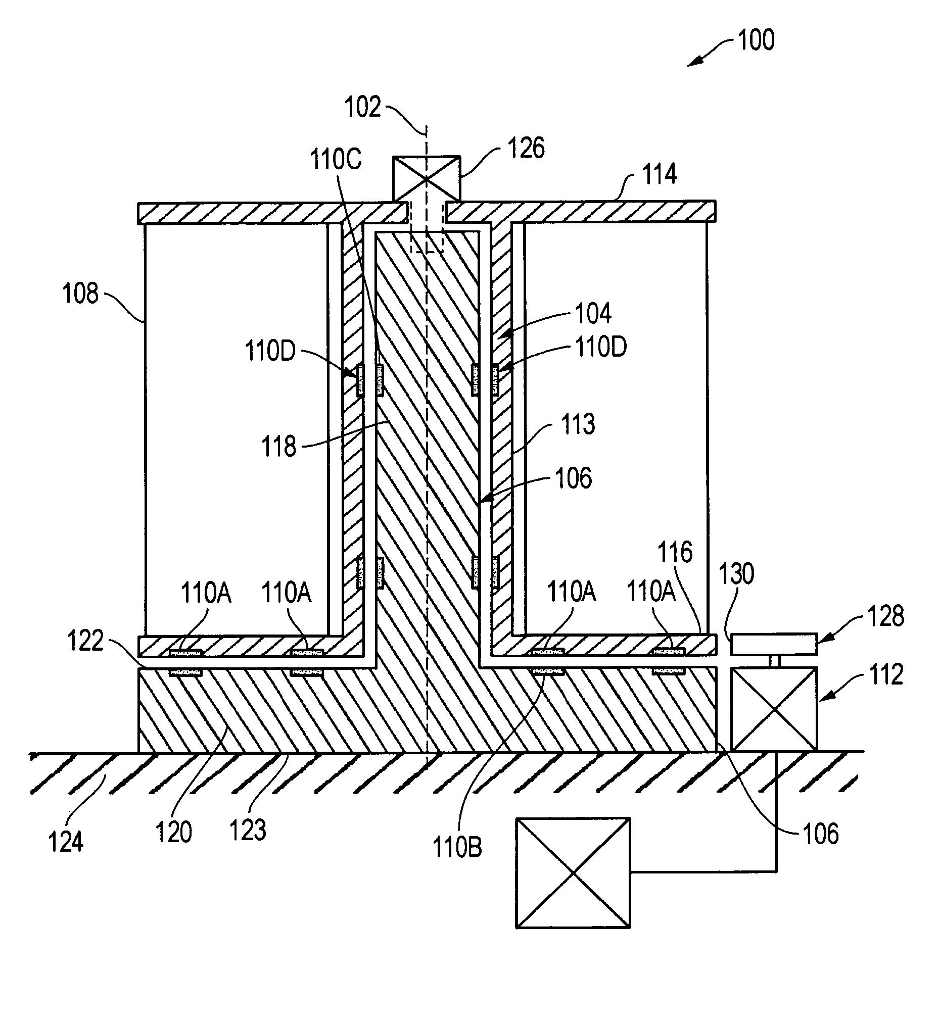
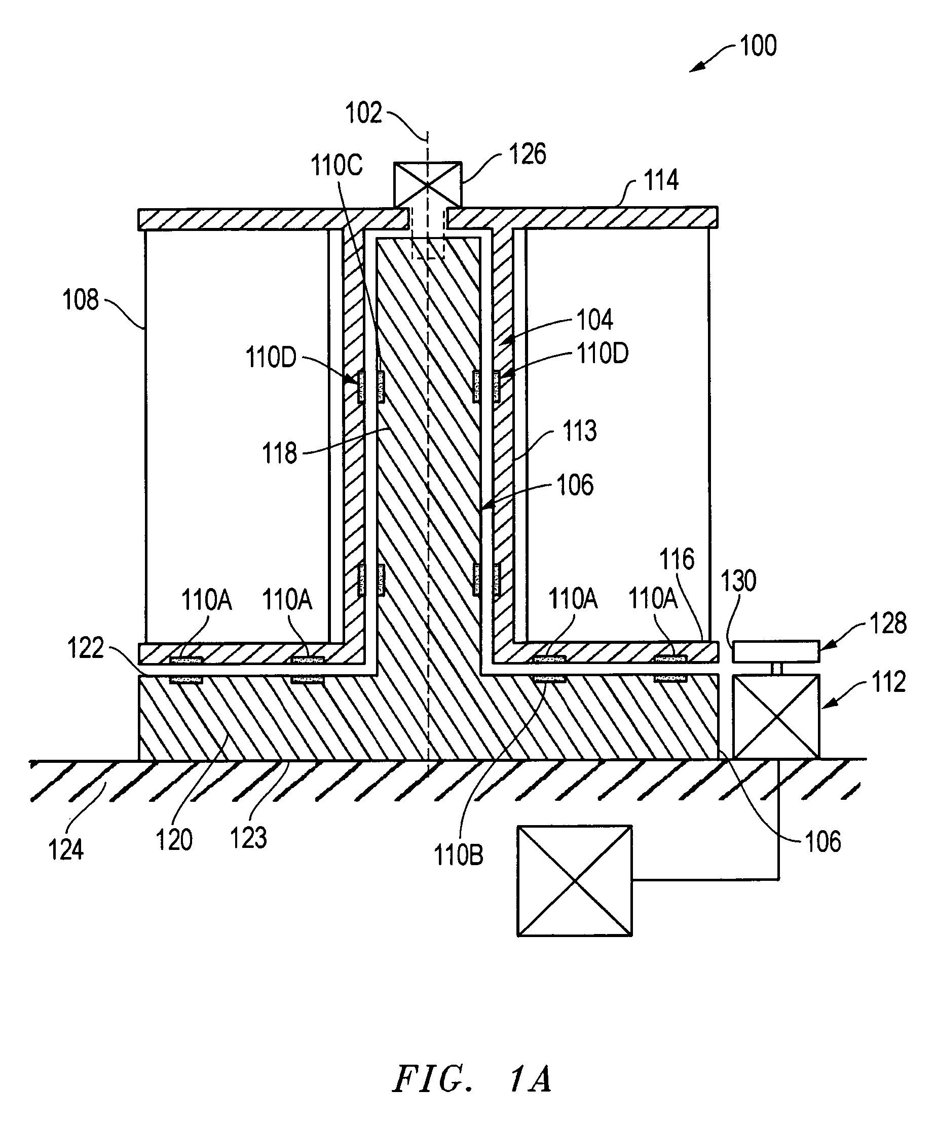
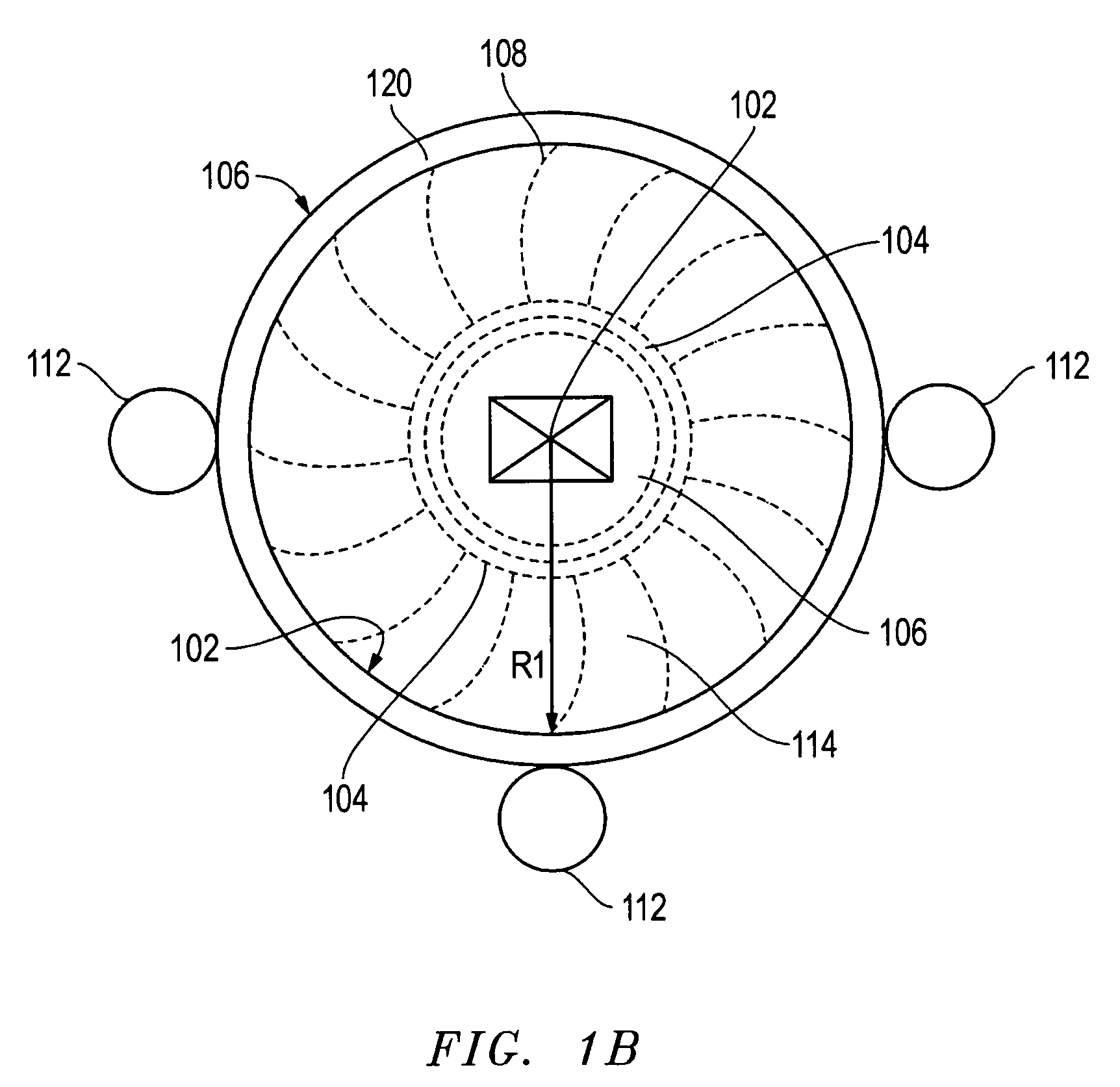
[0021]FIG. 1A is a schematic cross sectional view of a wind turbine 100, according to one embodiment. The wind turbine 100, as shown, is a vertical axis wind turbine. Therefore, a core axis 102 of the wind turbine 100 is substantially in a vertical plane relative to the Earth. The wind turbine 100 may have a turbine rotor 104 and a turbine support 106 within and concentric to the turbine rotor 104. The turbine rotor 104 rotates around the core axis 102 of the turbine support 106 in response to wind engaging one or more blades 108, shown schematically. The kinetic energy from the wind is captured by the blades 108 thereby rotating the turbine rotor 104. The turbine core support 106 may remain stationary as the turbine rotor 104 rotates around the axis 102. In order to reduce the effects of friction between the rotating turbine rotor 104 and the turbine support 106, one or more sets of magnets 110 are used to reduce the weight force of the turbine rotor 104 acting on the turbine suppo...


PUM


Abstract

A wind turbine having one or more sets of opposing magnets to create an opposing force between a turbine support and a turbine rotor great enough to form a space between them thereby reducing friction between the turbine support and the turbine rotor. The reduction of friction between the turbine rotor and the turbine support allows for an increase in energy production and scale of the wind turbines.

Description

FIELD OF INVENTION[0001]The field of invention relates to a wind turbine having one or more sets of magnets for reducing friction between a turbine rotor and a turbine support.RELATED PATENT APPLICATIONS[0002]The present application, Mazur, Wind Turbine is co-pending with the simultaneously filed patent application, Mazur, Wind Compressor.BACKGROUND OF THE INVENTION[0003]Wind turbines harness the kinetic energy of the wind and convert it into mechanical or electric power. Traditional wind turbines have a horizontal spinning axis that allowed blades of the wind turbine to rotate around the axis. As wind engages the blades, the blades move around the horizontal spinning axis of the wind turbine. The relative rotation of the blades to the horizontal axis may then be converted into energy.[0004]Recently vertical axis wind turbines have been used to harness the kinetic energy of the wind. Vertical axis wind turbines operate in the same manner as horizontal axis wind turbines; however, th...

Claims


Application Information

Patent Timeline
Patent Type & Authority Patents(United States)
IPC IPC(8): F03D9/00H02P9/04B64C27/00B64C11/00H02K7/09
CPCF03D3/0418F03D3/0472F03D11/0008H02K7/09F16C39/066F16C32/0431F03D3/005F03D9/002F03D9/003F05B2240/511F05B2240/941Y02B10/30Y02E10/74F16C2360/31F03D9/10F03D9/25F03D9/28F03D13/20F03D15/10F03D17/00F03D80/70F03D9/255Y02E10/72Y02E10/728Y02E70/30Y02P90/50F03D1/0675F03D3/062
Inventor MAZUR, ED
Owner HOVER ENERGY LLC
Why Eureka
Try Eureka