Data centre

a data centre and data technology, applied in the field of data centres, can solve the problems of data centre industry, high risk of refrigerant leakage, frequent cooling capacity and space limits, etc., and achieve the effect of reducing one or mor

Active Publication Date: 2013-08-20
BRIPCO
View PDF106 Cites 63 Cited by
  • Summary
  • Abstract
  • Description
  • Claims
  • Application Information

AI Technical Summary

Benefits of technology

[0029]Each rack room may have a floor and a plurality of rack storage areas on the floor, each rack storage area being arranged to accommodate a plurality of racks (for example arranged in a single row) in which a plurality of rack-mountable electronic components may be housed. The racks may be already installed in the data centre building or the data centre building may be provided without racks. The rack storage areas may include fixings or other means on the floor for facilitating correct positioning of the racks when installed. Each cold aisle may be positioned adjacent to a rack storage area. Each hot aisle may be positioned adjacent to a rack storage area. Cooling air is preferably transported to the one or more cold aisles under the control of the one or more air circulation systems.
[0078]Advantageously, the method provides a data centre that can be used in locations where the construction of a new building may not be possible or desirable, such as in city centres. The method may also be used by an organisation with an existing data centre or data room to easily upgrade the existing data centre or data room to use the present invention, thereby improving its efficiency. Alternatively, it may be used in a building that has been purpose-built to accommodate a data centre constructed according to the method.

Problems solved by technology

Current data centre technology is the summation of 30 years of innovation and engineering design thought and has come a long way in recent times. One key problem faced is how to cool a data centre effectively and efficiently.
These bring the advantage of concentrated cooling but carry a high risk of refrigerant leakage.
The data centre industry is also suffering from being unable to meet demand sufficiently quickly and from reacting to the need to make such data centres energy and space efficient.
Cooling capacity and space limits are frequently and repeatedly reached creating significant bottlenecks in IT businesses.
Building a new data centre to alleviate such bottlenecks and meet demand is time consuming.

Method used


Image

  • Data centre
  • Data centre
  • Data centre

Examples


Embodiment Construction

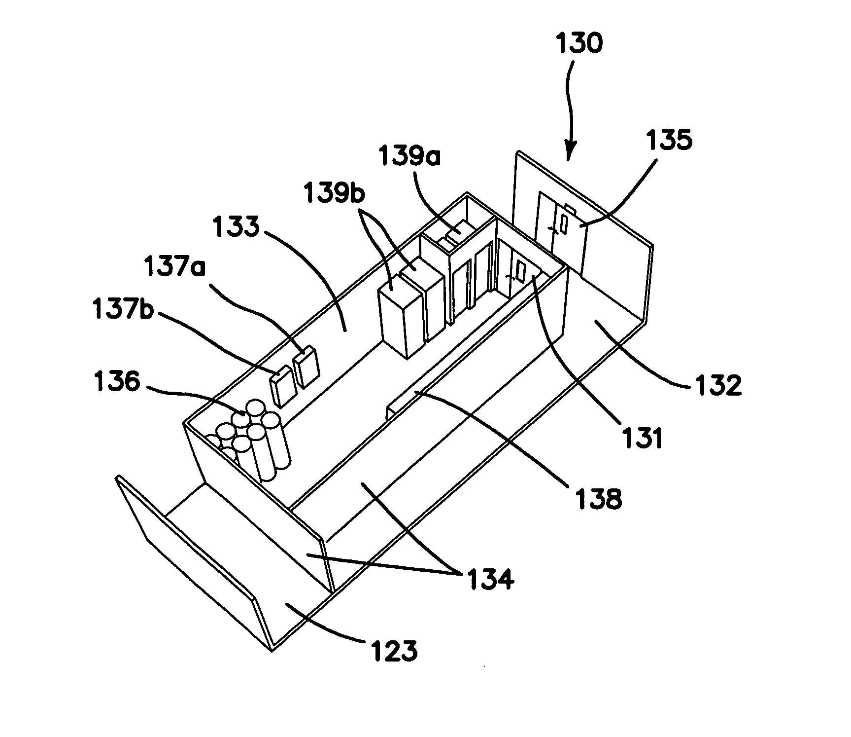
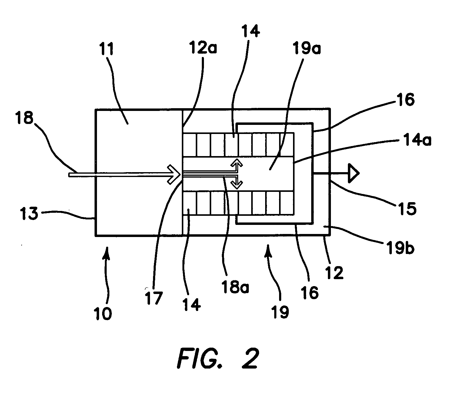
[0106]FIG. 2 shows a data centre building 10. The building 10 is rectangular with external walls 12. The building is divided into front and rear sections by an internal dividing wall 12a, located approximately one third of the length of the building from the rear external wall.

[0107]The rear section (on the left in FIG. 2) defines an air optimisation room 11, which provides a system of circulating cooling air in the building 10. Ambient air (represented by the light arrow 18) can enter the air optimisation room 11 through an ambient air intake 13 in the rear external wall. Ambient air 18 can be treated / cooled in the air optimiser room and this air 18a is then used for cooling. If the ambient air outside the building 10 is sufficiently cool, the ambient air may be used as cooling air, without requiring any active refrigerant-based cooling by the air optimisation room 11. Cooling air 18a passes into the front section of the building 10 through a controllable vent 17 in the internal di...


PUM

PropertyMeasurementUnit
heightaaaaaaaaaa
cross-sectional areaaaaaaaaaaa
areaaaaaaaaaaa

Abstract

A data center (100) includes at least one rack room (in for example module 140) having a floor and a plurality of rack storage areas on the floor, each rack storage area being arranged to accommodate a plurality of racks (143) in which a plurality of rack-mountable electronic components may be housed, one or more controllable air circulation systems (in for example module 122), one or more cold aisles (144) in the rack room, each cold aisle being adjacent to a rack storage area, and one or more hot aisles (145) in the rack room, each hot aisle being adjacent to a rack storage area. There may be a large air duct, in the form of a personnel corridor (123), for transporting, under the control of the one or more air circulation systems, cooling air, above the floor, to the one or more cold aisles. The air supply corridor / duct (123) may have a height greater than 1.5 m above the floor and a cross-sectional area of at least 2 m2 and a maximum dimension in the plane of the cross-section of less than 3 m.

Description

CROSS-REFERENCE TO RELATED APPLICATIONS[0001]The present application is a continuation of International Application PCT / GB2010 / 000759, filed Apr. 15, 2010, claims the benefit of International Application PCT / GB2009 / 051777, filed Dec. 29, 2009 and claims priority to United Kingdom Application GB0909584.5, filed Jun. 3, 2009, each of these applications being incorporated in its entirety herein by reference.BACKGROUND OF THE INVENTION[0002]The present invention concerns data centres, a method of cooling equipment in a data centre and also subject matter ancillary thereto. More particularly, but not exclusively, this invention concerns data centre buildings, for example provided in modular form. The invention also concerns a data centre building, a method of cooling electronic equipment in a data centre building, a method of constructing a data centre building, a method of extending an existing modular data centre building, a rack room building module for building a data centre, and a d...

Claims


Application Information

Patent Timeline
Patent Type & Authority Patents(United States)
IPC IPC(8): H05K7/20
CPCH05K7/20745F24F7/04G06F1/20H05K7/20136H05K7/20554F25D23/12E04H5/02H05K7/20181E04H2005/005H05K7/20H05K7/20145F24F7/007F24F7/013H05K7/20009H05K7/20536H05K7/1497H05K7/20754
Inventor ROGERS, PAUL
Owner BRIPCO
Why Eureka
Try Eureka