Aseptic or sanitary diaphragm valve

a diaphragm valve and sanitary technology, applied in the direction of diaphragm valves, engine diaphragms, operating means/release devices of valves, etc., can solve the problems of significant capital expense, complex and difficult to repair and maintain sanitary valves used in dairy industry and other food processing industries, and achieve the effect of simple construction

Inactive Publication Date: 2013-09-03
FELDMEIER EQUIP
View PDF3 Cites 4 Cited by
  • Summary
  • Abstract
  • Description
  • Claims
  • Application Information

AI Technical Summary

Benefits of technology

[0005]It is an object of the present invention to provide an aseptic or sanitary diaphragm valve arrangement of simple construction, and capable of being cleaned in place when installed in conduits for liquid food products, which is capable of controlling flow and / or pressure of the liquid product, and which avoids the drawbacks of the prior art.
[0006]It is another object to provide an aseptic or sanitary valve that is formed of a flat plate construction, avoiding the need to machine or manufacture complex surfaces within the valve cavity.
[0007]Another object is to provide a valve design permitting the valve to be constructed as a simple two-port valve or as a multiple-port valve.
[0008]It is a further object to provide a diaphragm valve that is capable of reliably regulating the flow pressure of fluids in a sanitary flow path.
[0011]In another preferred embodiment, the sanitary dual diaphragm valve may be designed for use as a diversion valve. A flat lower plate has an upper side which has a first round opening leading to a first tubular port on a lower side of the plate, a second opening leading to a second tubular port on the lower side of the plate, and a third round opening leading to a third tubular port on the lower side of the plate. A flat upper plate may be generally coextensive with the lower plate and is spaced above it so as to define a flow space between the two plates. The upper plate has a first cylinder situated above the first opening and in register with it. The cylinder rises upward above the second plate and has an open side that faces down towards the first opening. Similarly, a second cylinder is situated above the second opening in register with the second, corresponding opening. This cylinder rises upward above the upper plate and has a lower, open side facing the second opening. There are pistons, which may be free pistons, situated within the respective cylinders. These pistons are independently movable between a raised position and a lowered position. Within each of these cylinders, a flexible diaphragm is situated across the cylinder above the respective piston and another flexible diaphragm may be situated across the cylinder below such piston, and adapted to permit the associated piston to travel between its raised and lowered positions. For each cylinder, there is a valve member that has a stem aligned axially with the respective cylinder and the associated one of the first and second openings. A head member at an upper end of the respective stem is situated against an under side of the second or lower diaphragm of the associated cylinder. The valve member has a valve foot at the lower end of the stem and this aligned with the associated one of said valve openings and is adapted to close against the opening when the associated piston is in its lowered position, and to raise away from the associated opening when the piston is in its raised position. A mechanism, such as controlled compressed air, is employed for applying a closing force to the upper surfaces of the flexible diaphragm of each of the first and second (and possible further) cylinders. This urges the piston from its raised position to its lowered position to effect seating of the valve foot onto the respective valve opening, and controlled release of the closing force allows the associated piston to rise from its lower position to its raised position for lifting the valve foot from the associated valve opening. Air pressure may be applied to one or the other cylinder to effect closure of one flow path and opening of another flow path.

Problems solved by technology

No threaded connectors can be used anywhere that the liquid product flows, because of the difficulty in cleaning the threads.
In order to accommodate this requirement, the sanitary valves used in the dairy industry and other food processing industries have been complex and difficult to repair and maintain, and represent a significant capital expense.

Method used


Image

  • Aseptic or sanitary diaphragm valve
  • Aseptic or sanitary diaphragm valve
  • Aseptic or sanitary diaphragm valve

Examples


Embodiment Construction

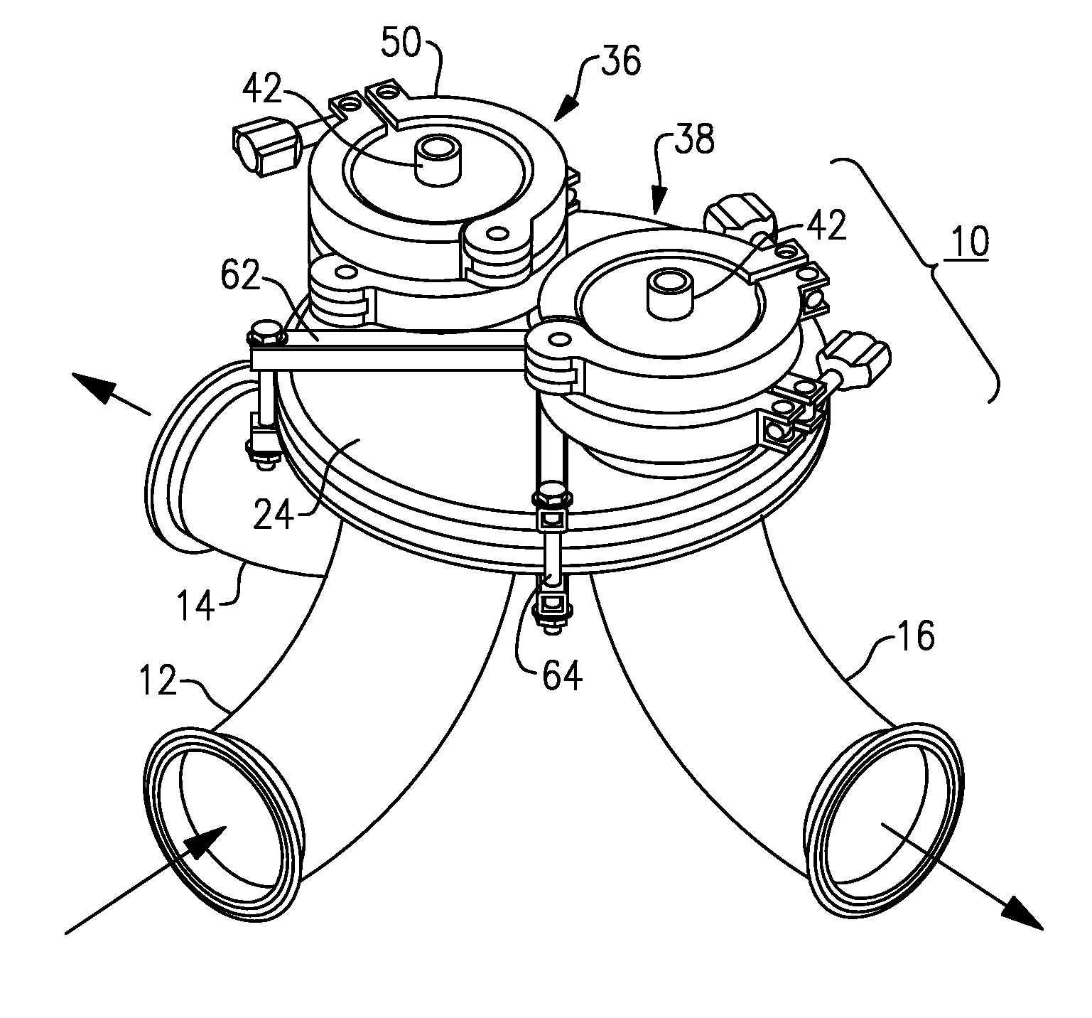
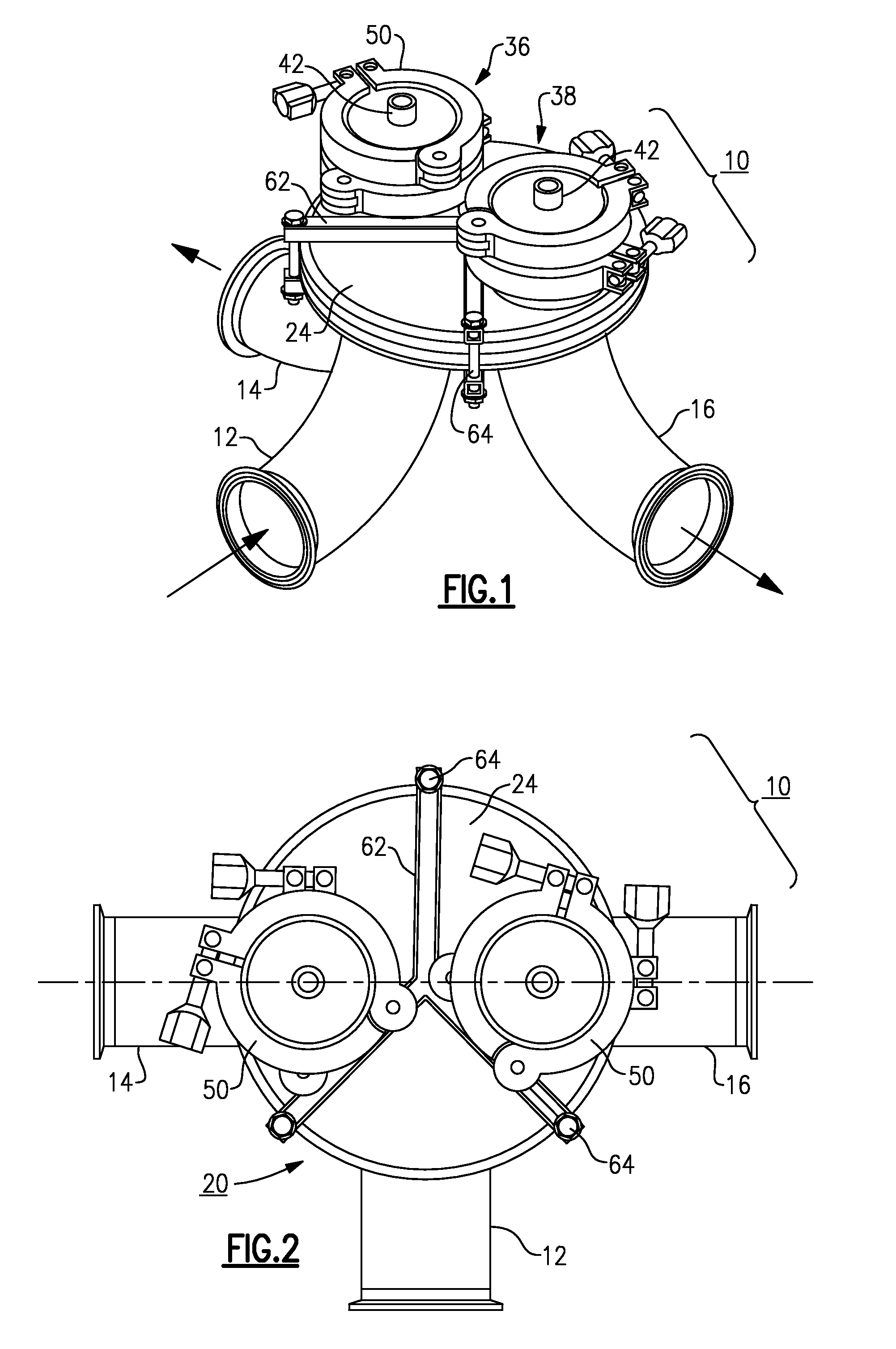
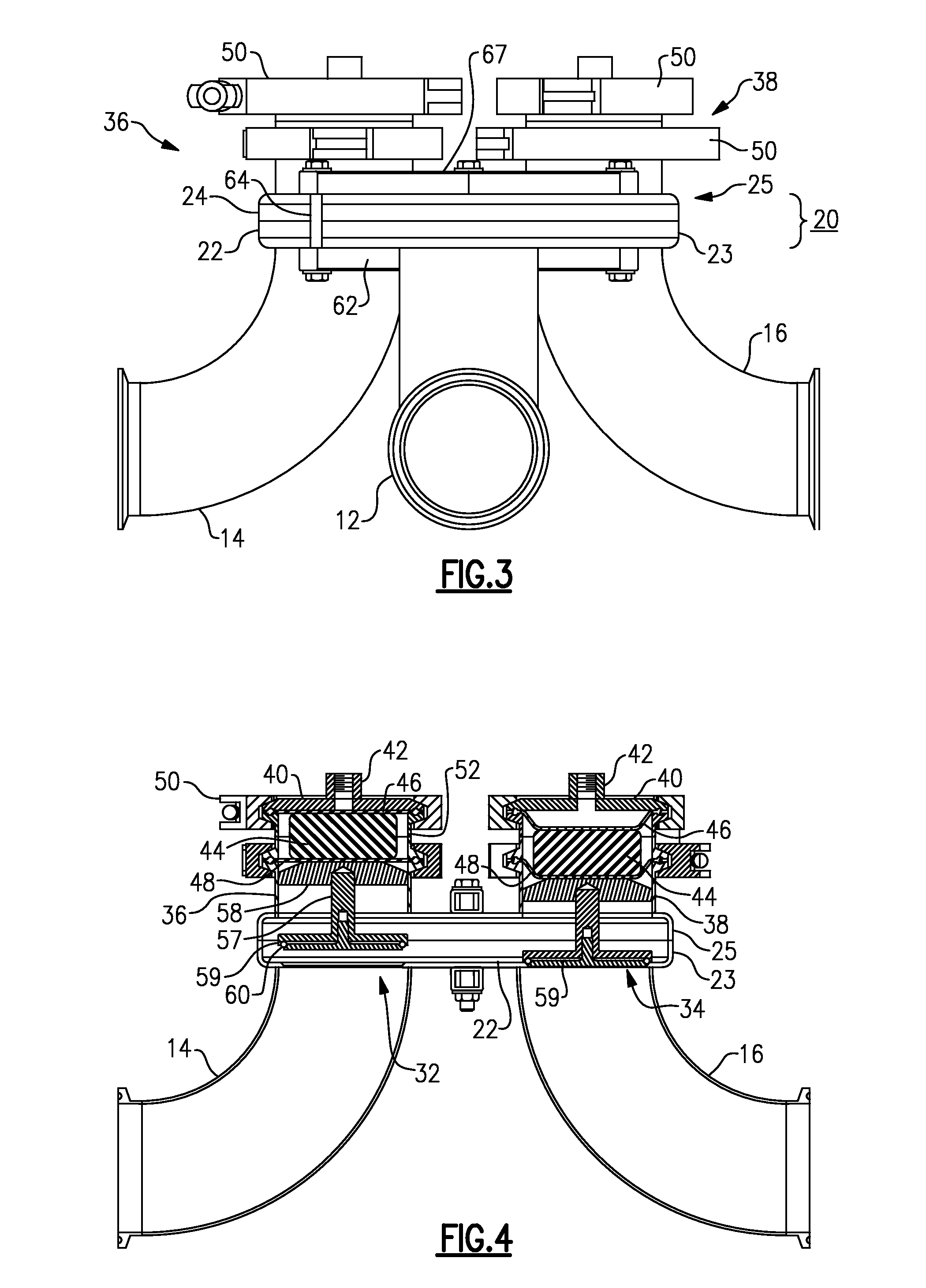
[0033]With initial reference to the embodiment illustrated in FIGS. 1 to 5, an aseptic valve or sanitary valve 10 of the present invention may be employed on a tubular sanitary conduit, suitable for processing a dairy product, such as milk or ice cream mix, another edible product such as fruit juice, sauce or soup, or a pharmaceutical product for human or veterinary use. The valve 10 may be useful in an aseptic process, e.g., where UHT pasteurization is employed.

[0034]The aseptic or sanitary valve 10 of this embodiment has one inlet and two outlets, and serves to switch fluid flow from an inlet tube 12 between a first outlet tube 14 and a second outlet tube 16. Other embodiments of this valve may have two or more controlled outlets. A valve body 20 in this embodiment is made in a clamshell design, with a lower plate or disk 22 with a circumferential flange 23 and a mating upper plate or disk 24 with a circumferential flange 25. The upper and lower plates 22, 24 are spaced a predeter...


PUM


Abstract

An aseptic or sanitary diaphragm valve has a valve body and at least one cylinder-actuated valve mechanism. A chamber is defined between a cylinder head and a plate or disk, which has a central bore or passage. A flexible diaphragm extends across the cylinder below the plate or disk. A piston within a cylinder is connected with a valve member foot portion, with a stem passing from the foot portion, penetrating the diaphragm, and passing through the bor or passage to the piston. A compression spring urges the piston to either its raised or lowered position, and air pressure may be used to lower or to raise the piston and the associated valve foot. An aperture in the cylinder can reveal a compromise of the diaphragms.

Description

[0001]This is a continuation-in-part of my patent application Ser. No. 12 / 766,009, filed Apr. 23, 2010 now abandoned.BACKGROUND OF THE INVENTION[0002]This invention relates to equipment for processing of liquids that must be kept aseptic, i.e., pharmaceuticals, dairy products, or other food products for human consumption. Such products would include milk, cream, ice cream mix, fruit juices and soups, or pharmaceuticals. The invention is more particularly concerned with sanitary valves of the type used in the dairy, food processing, and / or pharmaceutical industries, in which the flow of a fluid is to be regulated or diverted from one flow path to another. The invention is also concerned with diaphragm valves, that is, valves of the type in which a flexible membrane isolates the mechanical portions of the valve from the flow of fluid. The invention is more specifically concerned with a diaphragm valve of simple design and which can be cleaned and sterilized in place by the flow of a c...

Claims


Application Information

Patent Timeline
Patent Type & Authority Patents(United States)
IPC IPC(8): F16K11/22
CPCF16K11/20F16K31/1262F16K31/1221Y10T137/87893Y10T137/87877
Inventor FELDMEIER, ROBERT H.
Owner FELDMEIER EQUIP
Why Eureka
Try Eureka