
Debris flush system for balance shaft bearings

a technology of flushing system and balance shaft bearing, which is applied in the direction of auxillary lubrication, pressure lubrication, lubrication elements, etc., can solve the problems of bearing damage, engine failure, bearing damage, etc., and achieve the effect of reducing the flow resistance of the engine's pressurized lubrication network and reducing the pressure available to force oil

Active Publication Date: 2013-09-03
MD INVESTORS CORP
View PDF12 Cites 1 Cited by
  • Summary
  • Abstract
  • Description
  • Claims
  • Application Information

AI Technical Summary

Benefits of technology

The solution efficiently flushes contaminants from balance shaft bearings, reducing the risk of engine failure by ensuring clean oil supply and extending the life of the bearings through uniform cooling and debris removal, even at low engine speeds.

Problems solved by technology

Such build-phase contamination risks damage to balance shaft bearings, especially hydrostatic-type bearings at the extremities of current art lubrication passage networks where the oil passages terminate, leaving only bearing-to-journal running clearance as escape route for the oil and its possible contaminants to return back to the sump.
If the oil contains contaminants larger than can readily escape the very small oil film clearance gap, they will be trapped at the lubrication network terminal bearings, where cyclic motion of the shaft's journal can work them into the clearance gap and produce bearing damage.
Damage to balance shaft bearings can lead to engine failure, especially if oil pump functionality is impaired or lost.

Method used


Image

  • Debris flush system for balance shaft bearings
  • Debris flush system for balance shaft bearings
  • Debris flush system for balance shaft bearings

Examples


Embodiment Construction

[0016]While the present invention is described with reference to the embodiments described herein, it should be clear that the present invention should not be limited to such embodiments. Therefore, the description of the embodiments herein is illustrative of the present invention and should not limit the scope of the invention as claimed.

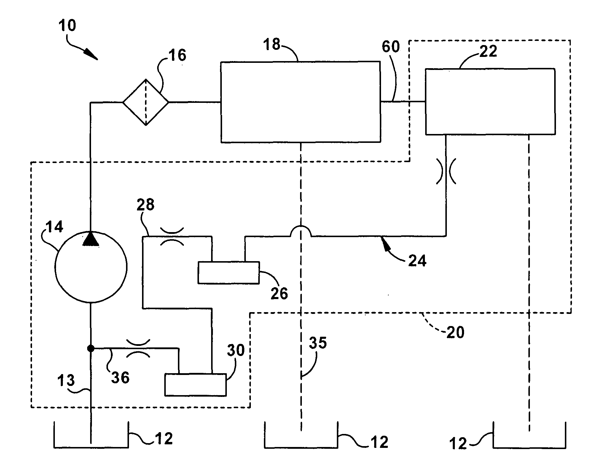
[0017]Reference will now be made in detail to the embodiments of the invention as illustrated in the accompanying figures. Referring now to FIG. 1, a schematic diagram of the oil filtration system 10 is shown. The system 10 may include a dirty oil sump 12 that feeds an oil pump 14. The pump 14 includes a first inlet passage 13 for fluid communication with the sump 12 and is operable to provide pressurized oil to the engine's lubrication network 18 of oil supply passages which includes a balance shaft bearing supply passage 22, also referred to as a bearing feed circuit. Additionally, as illustrated in FIG. 1, the pump 14 may be an integral componen...


PUM


Abstract

An engine oil filtration system including a pump operable to provide pressurized oil to the system is provided. A filter is in pressurized fluid communication with the pump and an engine lubrication network is in pressurized fluid communication with both the filter and an inlet of a balance shaft module. The balance shaft module also includes an outlet in pressurized fluid communication with the oil pump so that contaminated, pressurized oil may flow from the balance shaft module to the pump and filter for cleaning before being recycled to the engine's lubrication network.

Description

CROSS-REFERENCE TO RELATED APPLICATION[0001]This non-provisional patent application claims the benefit of U.S. Provisional Patent Application No. 60 / 839,210, entitled “DEBRIS FLUSH CHANNEL FOR BALANCE SHAFT MODULE,” filed Aug. 22, 2006, which is hereby incorporated in its entirety.FIELD OF THE INVENTION[0002]The present invention relates generally to a fluid filtration system, and more particularly, to an engine oil filtration system for reciprocating internal combustion-type engines having at least one balance shaft.BACKGROUND[0003]In many internal combustion engines, the engine crankshaft typically drives a balance shaft assembly to reduce engine vibration and noise due to the mass forces associated with the cyclic accelerations of reciprocating pistons and their connecting rods. Balance shafts are required to maintain substantially fixed angular timing relationships with the engine's crankshaft in order to fulfill their force cancellation functionality. And while single balance s...

Claims


Application Information

Patent Timeline
Patent Type & Authority Patents(United States)
IPC IPC(8): F01M1/00
CPCF01M1/02F01M11/02F01M2011/028
Inventor CHEVALIER, STEVEN J.TABBERT, DAVID E.
Owner MD INVESTORS CORP
Learn More