Vibration control equipment

a technology of vibration control equipment and damping rubber, which is applied in the direction of shock absorbers, mechanical equipment, transportation and packaging, etc., can solve the problems of rolling vibration generated around the driving shaft of the engine, interference of the vibration generating body with surrounding objects, etc., to improve the vibration resistance of damping rubber, easy assembly of vibration control equipment, and the effect of reducing production costs

Active Publication Date: 2013-09-03
PROSPIRA CORP
View PDF15 Cites 6 Cited by
  • Summary
  • Abstract
  • Description
  • Claims
  • Application Information

AI Technical Summary

Benefits of technology

[0028]With the vibration control equipment according to the present invention, the outer tubes of the damping rubbers are inserted into the fixing holes of the bracket member in the non-pressing state, and in order to dispose the position of the mold cavity portion in line with the vibrating direction of the vibration generating body, the circumferential position of the damping rubbers is determined with respect to the bracket member by the positioning portion. Therefore, it is possible to improve the vibration-resistance properties of the damping rubbers, while ensuring the support rigidity of the damping rubbers. Also, it is possible to easily assemble the vibration control equipment, and thus lower the production cost.

Problems solved by technology

However, there is a problem that if the support rigidity of the damping rubbers is lowered too much, the vibration generating body interferes with surrounding objects.
For example, in the case where the vibration control equipment is installed on the vehicle body through a bracket member and the plate member of the vibration control equipment is fixed to a lower portion of the engine, the vibration transmitted from the engine to the vibration control equipment causes rolling vibration to be generated around a driving shaft of the engine.

Method used


Image

  • Vibration control equipment
  • Vibration control equipment
  • Vibration control equipment

Examples


first embodiment

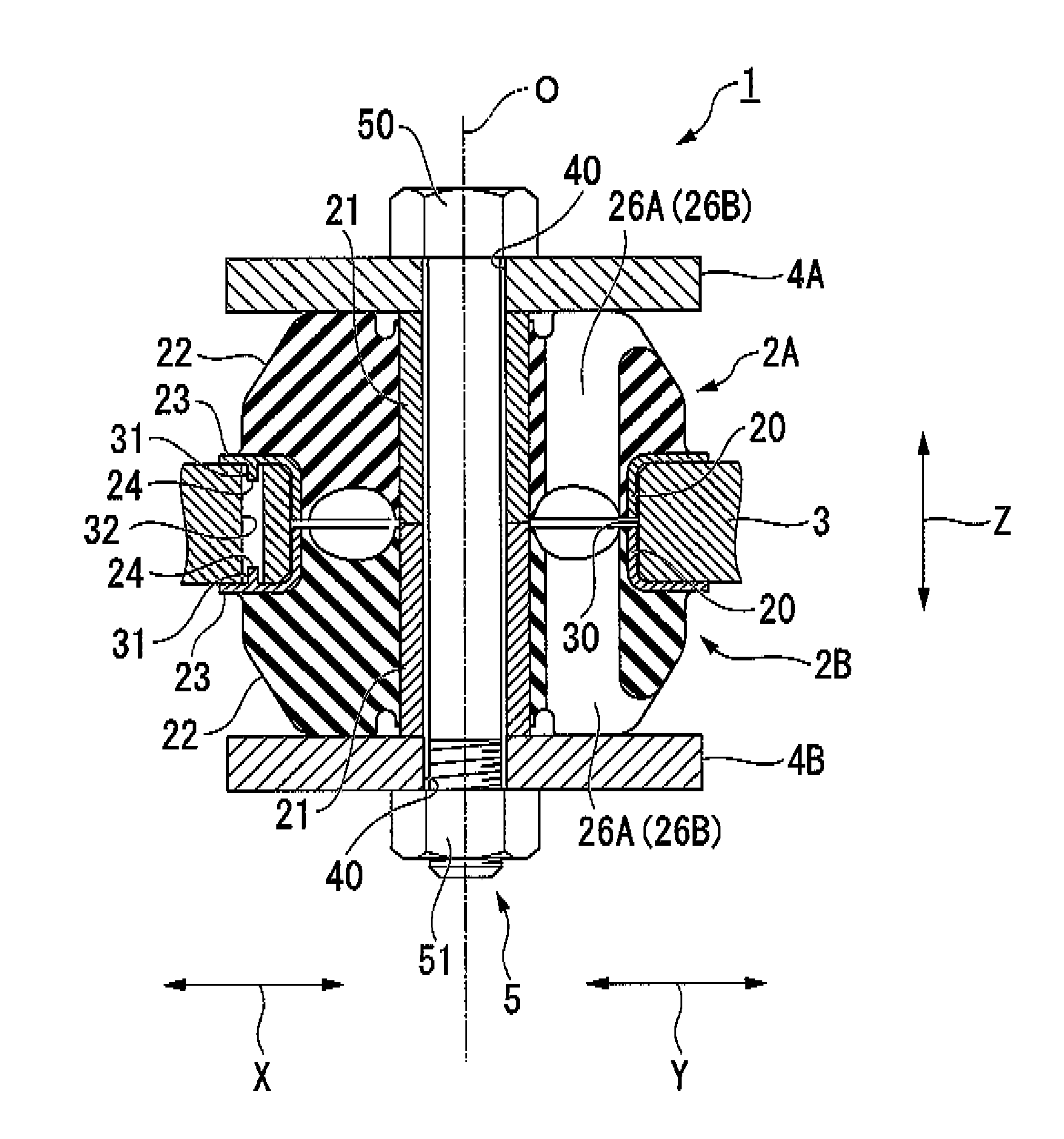
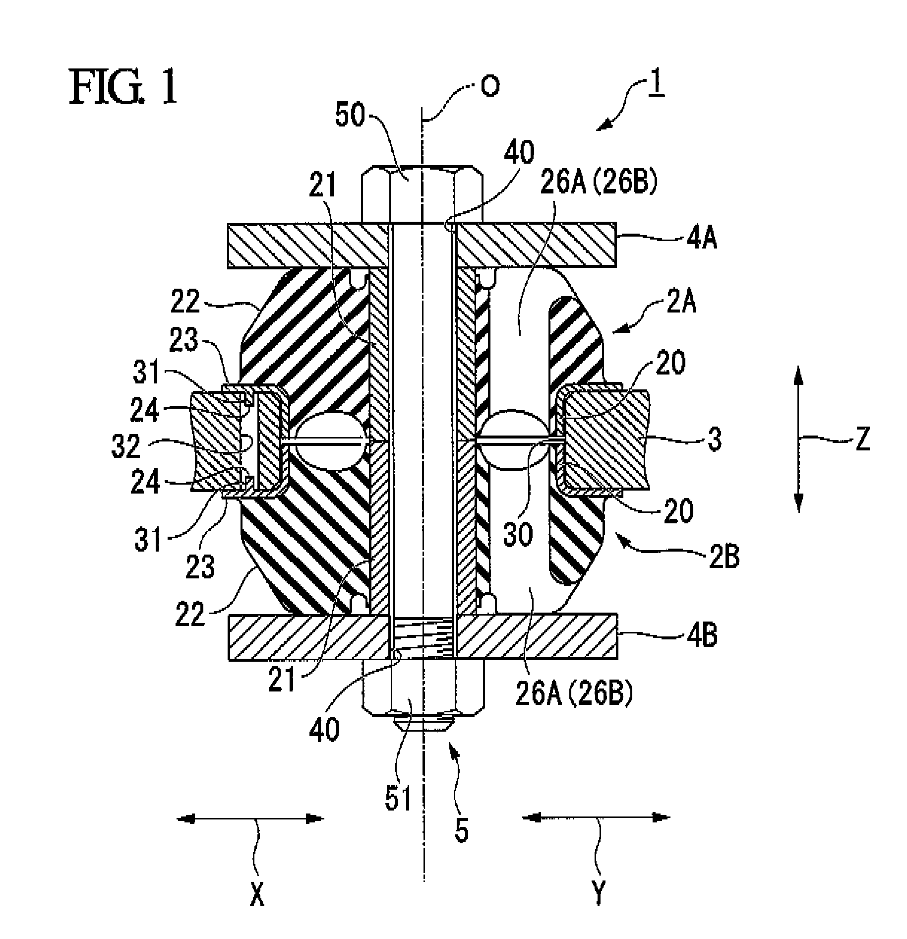
[0057]First of all, a vibration control equipment 1 according to the first embodiment will now be described with reference to FIGS. 1 to 3.

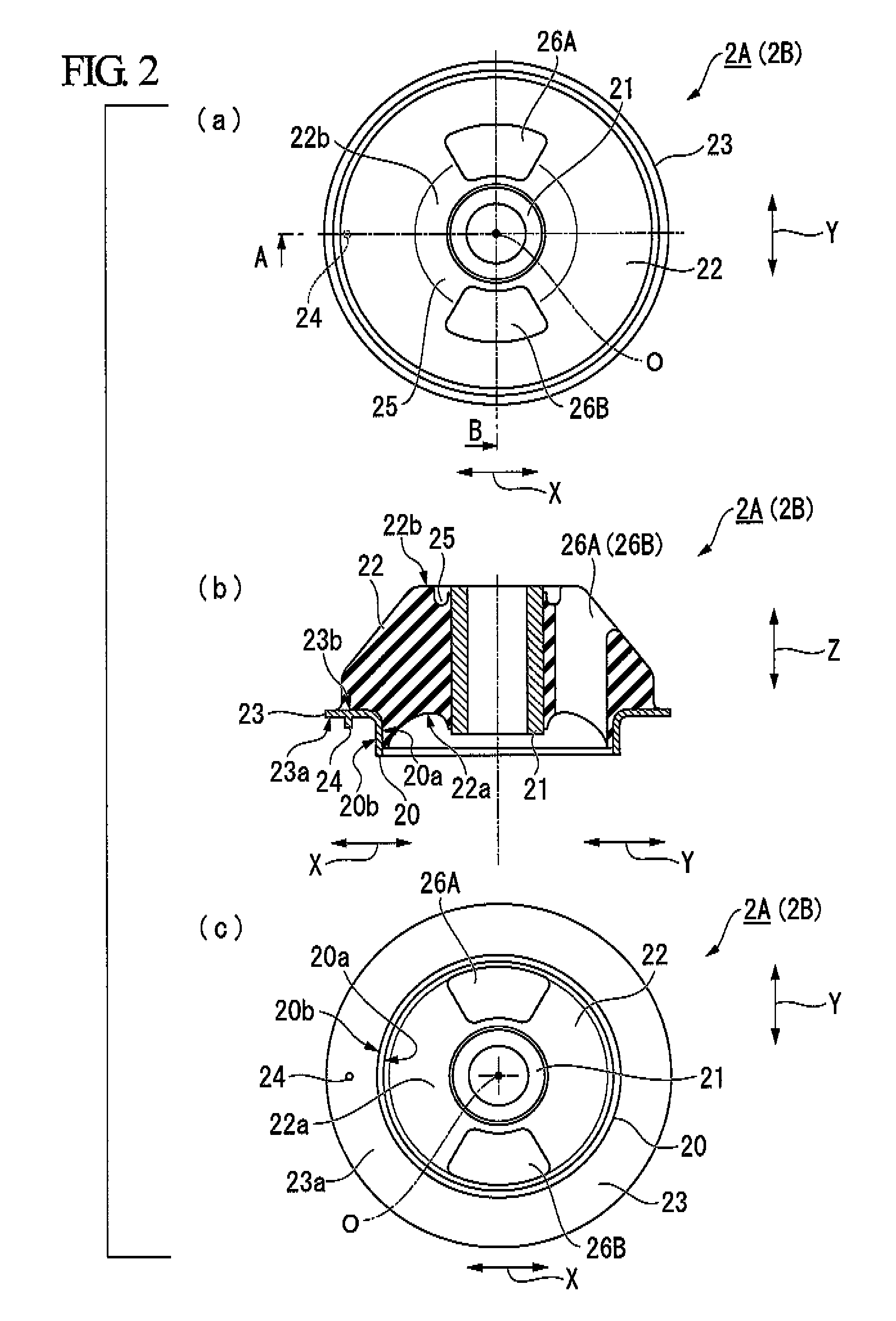
[0058]In the description below, the direction (horizontal direction) denoted by the symbol X shown in the figure is referred to as the front and rear direction, the direction (the vertical direction) denoted by the symbol Y shown in the figure is referred to as the left and right direction, and the direction (the vertical direction) denoted by the symbol Z shown in the figure is referred to as the upward and downward direction. Also, when viewing from one damping rubber 2A (2B), an opposite surface side (a lower side in (b) of FIG. 2) facing the other damping rubber 2B (2A) is referred to as an axial inner side, and a side (an upper side in (b) of FIG. 2) opposite to the surface is referred to as an axial outer side.

[0059]FIG. 1 is a cross-sectional view of a vibration control equipment 1 according to the first embodiment of the present invention...

second embodiment

[0094]Next, a vibration control equipment 101 according to a second embodiment of the present invention will now be described. Like parts are designated by the same reference numerals as the first embodiment, and the description thereof will be omitted herein.

[0095]FIG. 4 is a cross-sectional view of the vibration control equipment 101 according to the second embodiment.

[0096]FIG. 5 is a view showing an inner tube side segment body 110, in which (a) of FIG. 5 is a side view, (b) of FIG. 5 is a cross-sectional view, and (c) of FIG. 5 is a plan view when viewing at the axial inner side.

[0097]FIG. 6 is a view showing an outer tube side segment body 111, in which (a) of FIG. 6 is a plan view when viewing from the axial outer side, and (b) of FIG. 6 is a cross-sectional view.

[0098]The left half body (the left side of the central axis O) in FIG. 4, (b) of FIG. 5 and (b) of FIG. 6 is a cross-sectional view taken in the front and rear direction, while the right half body (the right side of ...


PUM

PropertyMeasurementUnit
inner diameteraaaaaaaaaa
natural vibration frequencyaaaaaaaaaa

Abstract

In a vibration control equipment 1 constituted by inserting an outer tube 20 of pair of damping rubbers 2A, 2B into an opening 30 of a bracket member 3, clamping the pair of damping rubbers 2A, 2B by means of plate members 4A, 4B, tightening a fastening member 5 for coupling the plate members 4A, 4B, and then compressing the rubber elastic bodies 22 of the damping rubbers 2A, 2B in the axial direction, the outside diameter of the outer tube 20 before tightening the fastening member 5 is smaller than the inside diameter of the fixing hole 30, the rubber elastic bodies 22 are compression deformed by tightening the fastening member 5 and thus a bracket member 3 is clamped by means of upper and lower flange portions 23, at least one of the rubber elastic bodies 22 is provided with mold cavity portions 26A, 26B and at least one of the pair of outer tubes 20 is provided with a positioning portion 24 for determining the circumferential position of the pair of damping rubbers 2A, 2B relative to the bracket member 3. According to the present invention, assembling work is facilitated by arranging the mold cavity portions in accordance with the direction of vibration and the production cost can be reduced.

Description

TECHNICAL FIELD[0001]The present invention relates to a vibration control equipment for use in a cabin mount or engine mount of machines for agriculture or construction.[0002]The present application claims priority from Japanese Patent Application No. 2007-095292, filed on Mar. 30, 2007, the content of which is hereby incorporated by reference into this application.BACKGROUND ART[0003]In general, when a vibration generating body, such as an engine, is mounted on a vibration receiving body, such as a vehicle body, a vibration control equipment is interposed between the vibration generating body and the vibration receiving body so as to prevent or suppress vibration from being transmitted from the vibration generating body to the vibration receiving body. As such a vibration control equipment, there is a sandwich-type vibration control equipment including a pair of damping rubbers and plate members placed on both sides of the damping rubbers. Each of the damping rubbers is composed of...

Claims


Application Information

Patent Timeline
Patent Type & Authority Patents(United States)
IPC IPC(8): B60G11/22F16F1/36
CPCF16F1/3735F16F3/0873
Inventor FUJIWARA, NOBUHIRO
Owner PROSPIRA CORP
Why Eureka
Try Eureka