Targeting guide with a radiopaque marker to facilitate positioning a bone plate on bone

a radiopaque marker and target guide technology, applied in bone drill guides, medical science, surgery, etc., can solve the problems of affecting the plate is susceptible to a variety of fractures and deformities, and the radioidal column is easy to shift, so as to facilitate the positioning of the bone pla

Active Publication Date: 2013-09-03
ACUMED
View PDF20 Cites 71 Cited by
  • Summary
  • Abstract
  • Description
  • Claims
  • Application Information

AI Technical Summary

Benefits of technology

[0003]Fixation of the fractured radius may be performed by internal fixation with a bone plate. The bone plate may be secured on the volar (or dorsal) surface of the distal radius with fasteners, such as bone screws or K-wires, among others. The volar side of the radius may be more accessible surgically and defines a distal pocket in which a distal portion of the bone plate may be disposed. Accordingly, in some cases, the bone plate may be less obtrusive and may produce less tendon irritation with volar placement, even if the bone plate is thicker and sturdier. Bone plates for fixation of the distal radius on either the volar or dorsal surface may include a narrower body portion disposed more proximally on the radius and a wider head portion disposed more distally.
[0004]Precise positioning of the bone plate on the radius (or other bone) may be critical for successful fracture fixation, particularly when the end of the bone is fractured into many pieces. In particular, the trajectory of each bone screw into bone is largely determined (variable-angle screws) or completely determined (fixed-angle screws) by where the plate is positioned on the bone, and thus meticulous placement of the bone plate can make screw installation much easier and more effective. Accordingly, a surgeon may spend more time reducing a fracture and positioning and re-positioning the bone plate on bone, than installing bone screws. For example, in some cases, a surgeon may spend about 45 minutes reducing the fracture and achieving the desired placement of the bone plate on the radius and then only about 15 minutes securing the bone plate with bone screws.

Problems solved by technology

The radius, like other bones, is susceptible to a variety of fractures and deformities.
A problem faced by surgeons when placing the bone plate on the bone prior to inserting screws is the tendency for the plate to shift while provisionally attaching it with one or more K-wires or clamps.
This leads to errors in plate placement, for example, as a result of the plate pivoting and / or sliding.
Errors in plate placement for the distal radius can cause screw trajectories to extend into unintended areas, such as into the joint distally or into soft tissue radially.
This approach can prove difficult because forceps and bone clamps do not provide a rigid attachment to the plate, so the bone plate may shift in position.
It can be difficult to align the bone plate with features of the bone to achieve optimal plate position.
However, the bone plate may be relatively short and the bone may be wide and tapered where the bone plate is placed, which makes alignment of the plate and bone axes inaccurate.
However, the handle generally is not designed properly to enable fluoroscopy-guided positioning and re-positioning of a bone plate on a target bone, and attachment of the bone plate when situated properly.
For example, the handle may be unsuitable for fluoroscopy because the handle is designed to be grasped too close to the plate, which places the surgeon's hand in the field of view and / or exposes the surgeon's hand to excess radiation.
Also, the handle may obscure or otherwise interfere with fluoroscopic viewing of the bone plate.
Furthermore, the handle may fail to provide suitable orientation features that enable a surgeon to select an informative fluoroscopic view of the bone plate and bone with confidence.
The handle also may fail to offer any alignment features for use when checking or adjusting the alignment of the bone plate with bone, particularly if the handle is formed of plastic, which is generally radiolucent.
However, surgeons can have difficulty predicting how plate position will relate to screw trajectory without installing screws.
This trial-and-error approach can be slow and frustrating to the surgeon, and may damage bone and the joint.
A surgeon may have difficulty determining how far distally to place the bone plate on the volar bone surface.
This approach, like the related approach described in the preceding paragraph, can be time-consuming and frustrating for the surgeon and damaging to bone.
Accordingly, if the styloid screw trajectory is undesirable, the plate cannot be shifted in position to correct the styloid screw trajectory without taking out all of the distal screws.

Method used


Image

  • Targeting guide with a radiopaque marker to facilitate positioning a bone plate on bone
  • Targeting guide with a radiopaque marker to facilitate positioning a bone plate on bone
  • Targeting guide with a radiopaque marker to facilitate positioning a bone plate on bone

Examples


example 1

Exemplary Radiographic Images

[0096]This example describes exemplary radiographic images that may be generated with an exemplary bone fixation system disposed on an exemplary bone; see FIGS. 12-14.

[0097]Relative radiopacity is indicated in the images by shading, with bone 64 being less radiopaque than bone plate 52, which in turn is less radiopaque than markers 252-256 and extension portion 142 of handle 56. Structures that block X-rays most efficiently are darkest in the images, and would be lightest in negative versions of the images.

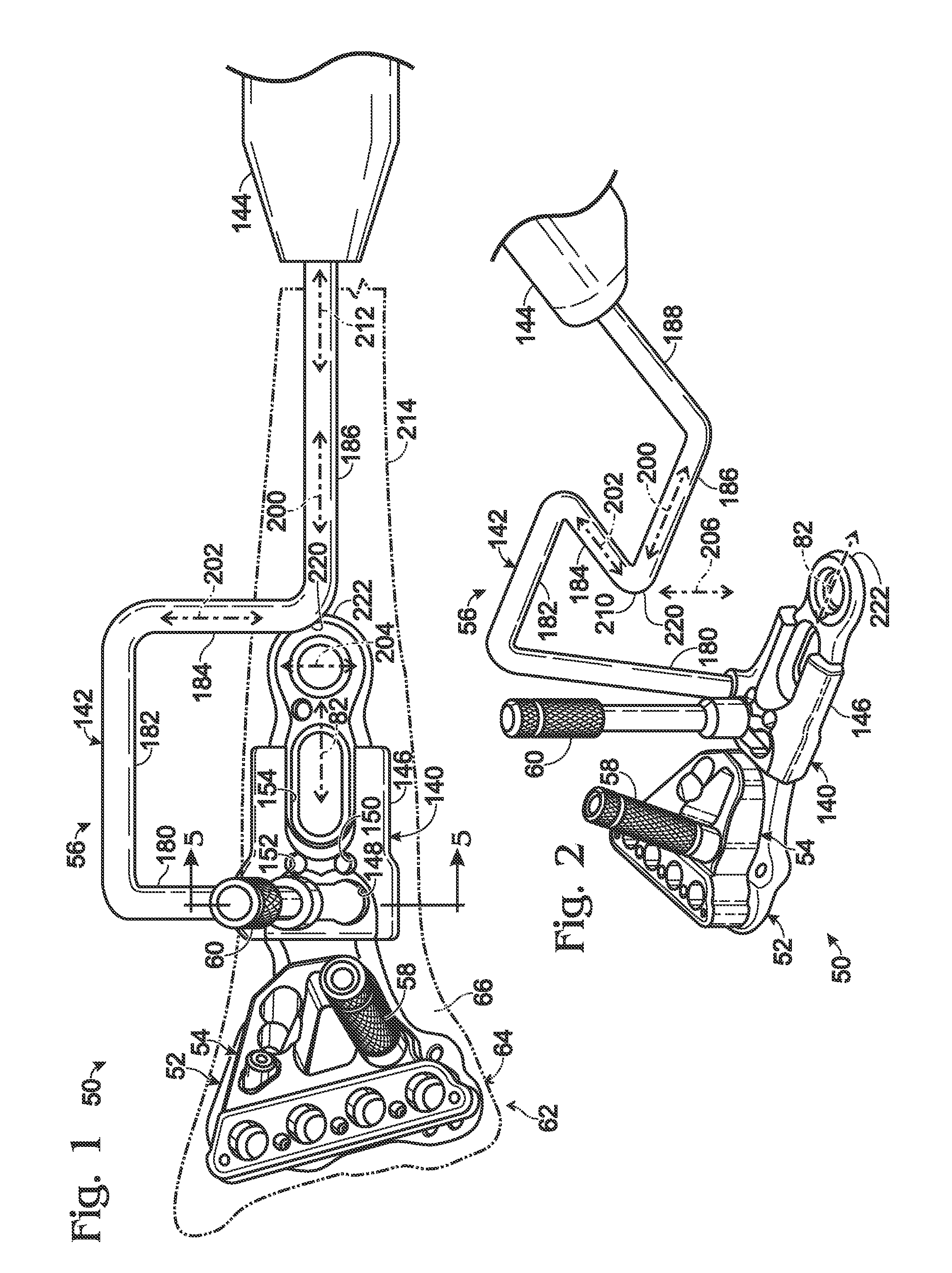
[0098]FIG. 12 shows an exemplary radiographic image 320 of bone fixation system 50 and radial bone 64 (see FIG. 1). Fasteners 58, 60 are not shown to simplify the presentation. Image 320 may be generated using a radiation beam having a beam axis that is orthogonal to a plane defined by bone plate 52, and is directly along an anterior-posterior through the bone. A surgeon can find the proper beam axis for the image shown by adjusting the beam axis until...

example 2

Selected Embodiments I

[0101]This example describes selected embodiments of the present disclosure involving a handle, presented as a series of indexed paragraphs.

[0102]1. A method of situating a bone plate on bone, comprising: (A) connecting a targeting guide and a handle to a bone plate to form an assembly; (B) detecting one or more radiographic images of the assembly with the assembly disposed on a surface region of a bone; and (C) positioning the assembly on the surface region based on a pair of nonparallel axes defined in the images by the targeting guide and the handle.

[0103]2. The method of paragraph 1, wherein the step of positioning the assembly is based on first and second axes arranged obliquely to each other.

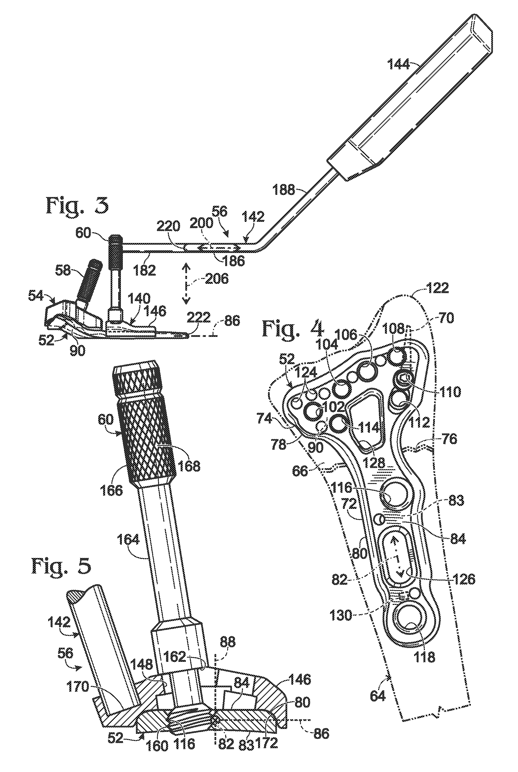
[0104]3. The method of paragraph 2, wherein the first axis is defined by a relatively radiopaque pin attached to and disposed in a relatively radiolucent body of the targeting guide

[0105]4. The method of paragraph 2, wherein the first axis is configured to extend near...

example 3

Selected Embodiments II

[0152]This example describes selected embodiments of the present disclosure involving a targeting guide in the form of a guide block, presented as a series of indexed paragraphs.

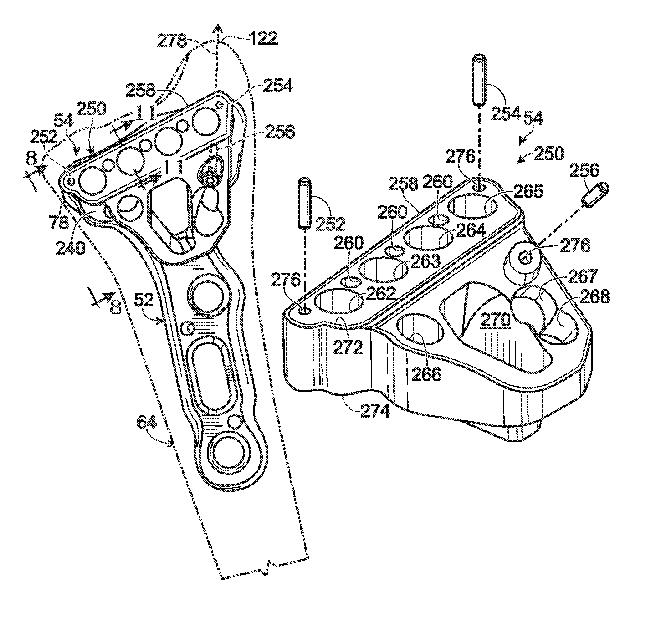
[0153]1. A method of bone fixation, comprising: (A) selecting a bone plate including an outer surface region and defining a plurality of apertures; (B) selecting a guide block defining a plurality of openings and including a radiolucent body and at least one elongated, radiopaque marker disposed in and affixed to the radiolucent body; (C) attaching the guide block to the bone plate with the guide block over the outer surface region of the bone plate and such that openings of the guide block are adjacent to and in coaxial alignment with apertures of the bone plate, wherein attached is performed after the at least one marker is affixed to the radiolucent body; (D) disposing the bone plate on bone; (E) securing the bone plate to the bone with fasteners placed in one or more of the apertur...


PUM


Abstract

Bone fixation system, including methods, apparatus, and kits, and comprising a bone plate and at least one instrument that attaches to the bone plate and provides at least one radiopaque region to facilitate positioning the bone plate on bone visualized by radiographic imaging. The instrument may be a handle assembly and / or a targeting guide.

Description

CROSS-REFERENCES TO PRIORITY APPLICATIONS[0001]This application is based upon and claims the benefit under 35 U.S.C. §119(e) of U.S. Provisional Patent Application Ser. No. 61 / 386,921, filed Sep. 27, 2010, and U.S. Provisional Patent Application Ser. No. 61 / 390,120, filed Oct. 5, 2010, each of which is incorporated herein by reference in its entirety for all purposes.INTRODUCTION[0002]The radius (or radial bone) is one of two long bones found in the human forearm. The radius, like other bones, is susceptible to a variety of fractures and deformities. For example, distal fractures of the radius are a common result, particularly among the elderly, of forward falls with the palms facing downward. In such falls, force exerted on the distal radius at impact frequently produces dorsal displacement of one or more bone fragments created distal to the fracture site.[0003]Fixation of the fractured radius may be performed by internal fixation with a bone plate. The bone plate may be secured on...

Claims


Application Information

Patent Timeline
Patent Type & Authority Patents(United States)
IPC IPC(8): A61B17/88
CPCA61B17/1728A61B17/8061A61B17/808A61B2017/1782A61B2019/5466A61B17/1782A61B2090/3966
Inventor HUEBNER, RANDALL J.FEDERSPIEL, JOSHUA P.CONNORS, CAROL-LYNN E.RITTER, JAMES C.
Owner ACUMED
Why Eureka
Try Eureka