

Photovoltaic cell with non-miscible electrolytes
a photovoltaic cell, non-miscible technology, applied in the field of photovoltaic cells, can solve the problems of low electrical conductivity, low efficiency of cells in particular, and high cos
Inactive Publication Date: 2013-09-03
COMMISSARIAT A LENERGIE ATOMIQUE ET AUX ENERGIES ALTERNATIVES
View PDF9 Cites 1 Cited by
- Summary
- Abstract
- Description
- Claims
- Application Information
AI Technical Summary
Benefits of technology
The new photovoltaic cell structure described in this patent offers greater transparency, a stronger design, and a lower production cost. It overcomes the issue of shading associated with metallizations and allows for the use of non-transparent electrodes, providing better conductivity. Additionally, this structure offers greater flexibility for integration with other materials and provides better collection of electric charges from the photocurrent generated. The use of ionic liquids in the photovoltaic cell further increases the range of operating temperatures and allows for a wider absorptions spectrum.
Problems solved by technology
Such cells in particular have the disadvantages of relatively low efficiency (on the order of 4%) when they are based on a solid polymer, and have a certain instability when the titanium dioxide particles are placed in an electrolytic solution, due to the breakdown and evaporation of the organic solution.
Finally, such a cell has the disadvantages of comprising only a single transparent face for collecting light, and the electrode located at the level of this transparent face is based on a material that is generally expensive and / or has a low electrical conductivity.
Method used
View moreImage
Smart ImageViewing Examples

Examples
first embodiment
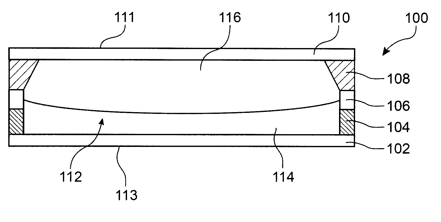
[0046]FIG. 1 is a cross-section view of a photovoltaic cell with non-miscible electrolytes
second embodiment
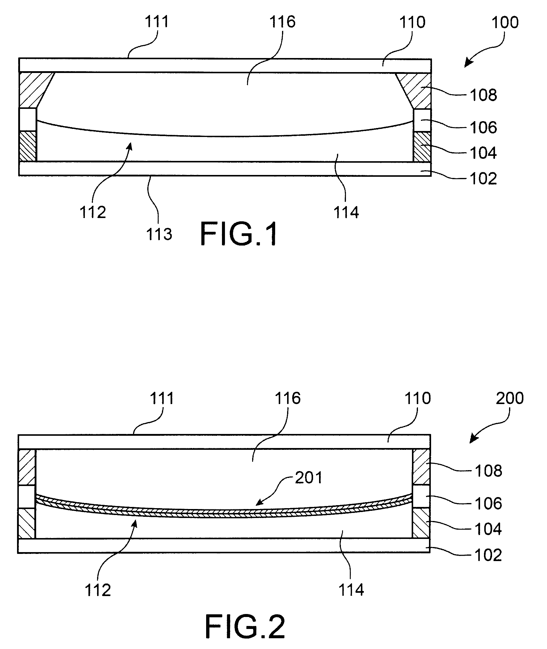
[0047]FIG. 2 is a cross-section view of a photovoltaic cell with non-miscible electrolytes according to a
[0048]Identical, similar or equivalent parts of the various figures described below have the same numeric references for the sake of consistency between the figures.
[0049]In order to make the figures easier to read, the various parts shown in the figures are not necessarily done so according to a uniform scale.
[0050]The various possibilities (alternatives and embodiments) should be understood as not being exclusive of one another and can be combined with one another.
Login to View More PUM
 Abstract
A photovoltaic cell including at least: a closed chamber including two end walls arranged opposite one another, with at least one being intended to receive incident light radiation, and including at least one side wall formed by at least one stack of a first electrode and a second electrode electrically insulated from one another, the first electrode and second electrode each having an annular shape each being disposed at a periphery of a respective one of the two end walls; at least two non-miscible electrolytes placed in the closed chamber, forming two superimposed layers of which one is in contact with the first electrode and the other is in contact with the second electrode; and a photoactive layer, placed in the closed chamber, that achieves a photovoltaic conversion of energy of the incident light radiation.
Description
TECHNICAL FIELD[0001]The invention relates to the field of photovoltaic cells, and more specifically that of small photovoltaic cells intended for applications requiring low energy, for example on-board nomadic devices (portable telephones, multimedia reader, etc . . . ).PRIOR ART[0002]It is known to produce a photovoltaic cell comprising a first electrode stacked with a first layer based on a semiconductor of type N, for example silicon, a second layer based on a semiconductor of type P and a second electrode, thus forming a PN junction arranged between two electrodes. The electrodes make it possible to collect the current created by the PN junction by receiving photons of incident light.[0003]Gratzel cells are organic photovoltaic cells. They are nanocrystalline photovoltaic cells comprising titanium dioxide electron acceptor particles coated with a photosensitive dye, called a “sensitizer”, in the form of a monomolecular layer. These particles are placed in an electrolytic soluti...
Claims
Login to View More Application Information
Patent Timeline
 Patent Type & AuthorityPatents(United States)
IPC IPC(8): H01L31/0203H01L31/048
CPCH01G9/2004H01G9/2068Y02E10/542Y02P70/50
InventorFUSALBA, FLORENCEREMIAT, BRUNO
OwnerCOMMISSARIAT A LENERGIE ATOMIQUE ET AUX ENERGIES ALTERNATIVES