Light-emitting diode lamp

a technology of light-emitting diodes and lamps, which is applied in the direction of telephonic communication, electric variable regulation, lighting and heating apparatus, etc., can solve the problems of disadvantageous light sources, not being able to be exploited indoors, and the illuminator must be constantly shaken

Inactive Publication Date: 2013-09-03
SAMOILENKO IURII N +1
View PDF5 Cites 30 Cited by
  • Summary
  • Abstract
  • Description
  • Claims
  • Application Information

AI Technical Summary

Benefits of technology

[0012]The proposed technical solution allows to ensure highly efficient performance of a light-emitting diode lamp due to removal of a diode bridge, as well as a shunt resistor and current-limiting resistor from the circuit in the voltage down-converter, which results in the reduction of consumption of active power.
[0015]According to yet another proposed embodiment, in order to protect the light-emitting diodes from switching surges and overvoltages resulting from voltage fluctuation in the power network, reference diodes connected in series and in opposite directions should be installed in parallel to the light-emitting diodes.

Problems solved by technology

Such an LED source is disadvantageous in that its illuminator has to be constantly shaken.
A disadvantage in using this lamp is that it can not be exploited indoors.
Such a light source is disadvantageous due to significant electricity consumption.
A disadvantage of this device is considerable electric energy consumption a part of which is lost in the shunt resistor.

Method used


Image

  • Light-emitting diode lamp
  • Light-emitting diode lamp
  • Light-emitting diode lamp

Examples


Embodiment Construction

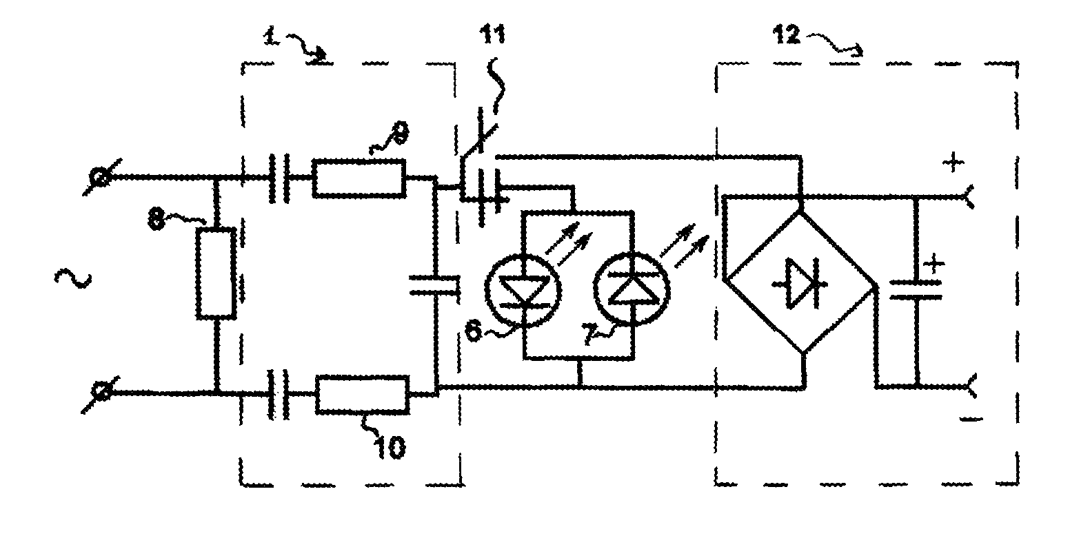
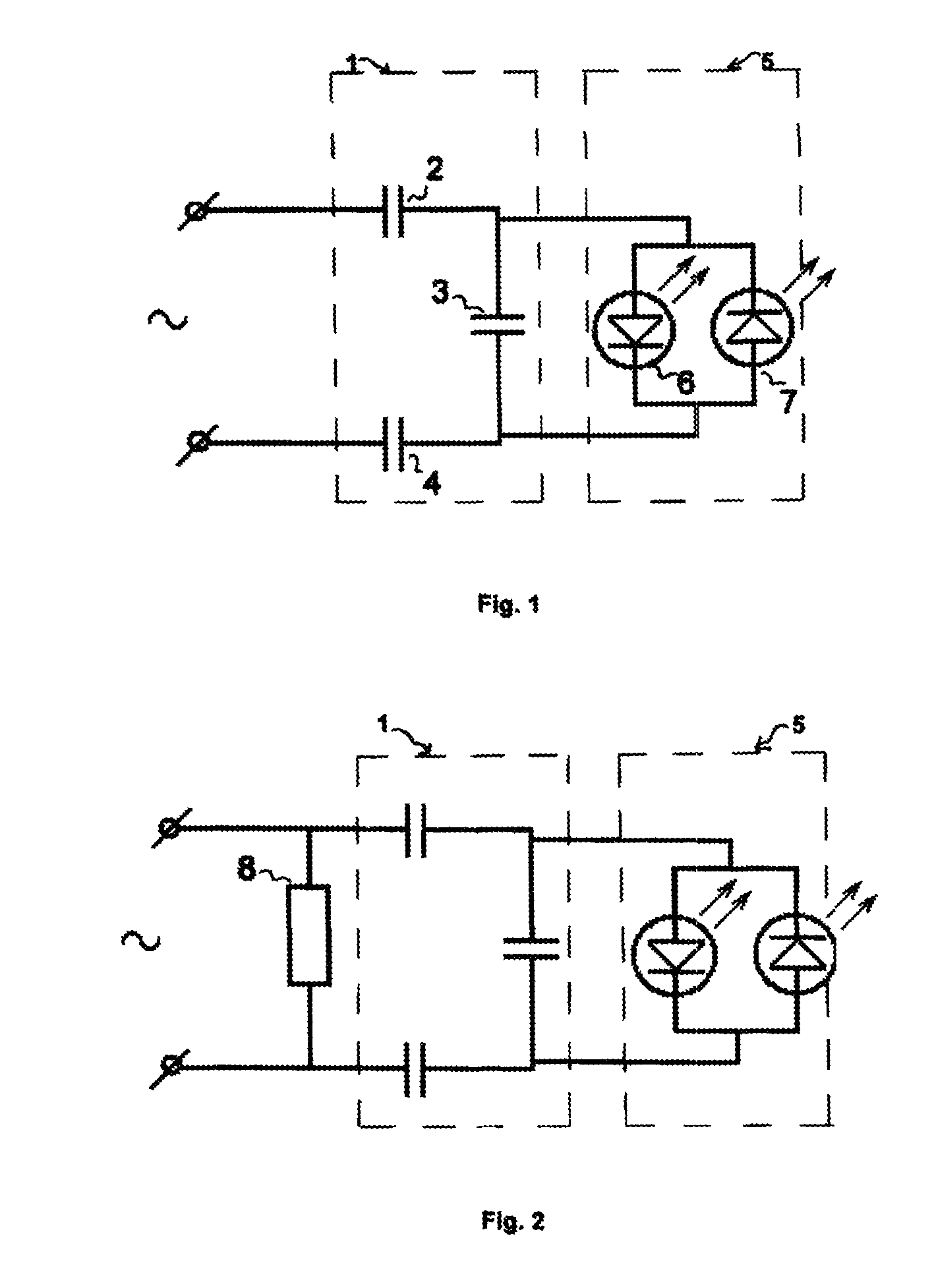
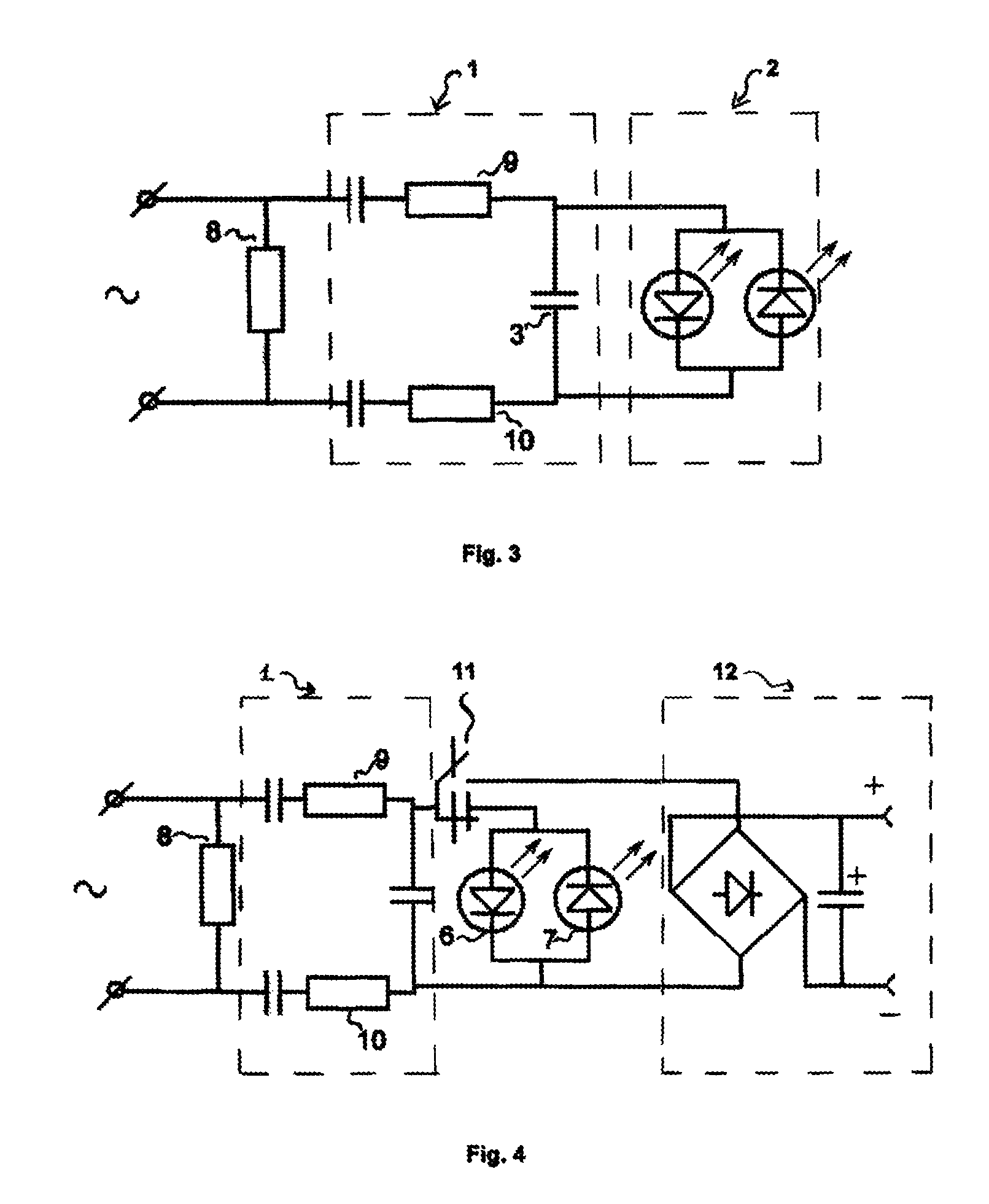
[0022]As shown in FIG. 1, the light-emitting diode lamp according to the invention comprises a voltage down-converter 1 which, according to the invention, is made up of a chain of capacitors 2, 3, 4 connected in series, one of which is a power take-off capacitor (the power take-off capacitor is marked with reference number 3 on the drawings 3).

[0023]The light-emitting diode lamp according to the invention comprises at least one pair 5 of light-emitting diodes 6, 7 installed in parallel opposition and connected to the power take-off capacitor 3. The number of pairs 5 of light diodes in the lamp is chosen depending on the conditions in which a respective level of lighting needs to be achieved.

[0024]In order to discharge collected charge in the capacitors 2, 3, 4, according to one preferred embodiment, a resistor 8 can be installed at the input of the voltage converter 1 as shown in FIG. 2. The rated resistance of the resistor 8 is set in the range from ones to tens of mOhm.

[0025]At th...


PUM


Abstract

The invention relates to electric lighting facilities powered from an external electrical network. The light-emitting diode lamp comprises a step-down voltage converter (1) made up of a chain of capacitors (2, 3, 4) connected in series, one of which is a power take-off capacitor (3) and is connected to at least one pair (5) of inverse-parallel connected light-emitting diodes (6, 7). The invention makes it possible to achieve extremely low electrical energy consumption for lighting, ensure optimum performance, and use the circuit for the additional function of supplying power to external users of, for example, mobile telephones.

Description

FIELD OF THE INVENTION[0001]The invention relates to light sources and particularly deals with light-emitting diode (LED) lamps which can be used for both outdoor and indoor lighting and have ultra-low active energy consumption.BACKGROUND OF THE INVENTION[0002]Light-emitting diode lamps with white light-emitting diodes embedded within a single housing are known from the background art (RU,2234638,C1).[0003]Such an LED source is disadvantageous in that its illuminator has to be constantly shaken.[0004]There is also a lamp powered from solar energy, comprising a panel with photovoltaic cells, an electric storage battery, a lighting unit and a control unit, characterised in that it consists of a single modular housing comprising a panel with photovoltaic cells, an electric storage battery, a control unit and a lighting unit made as a CCD array, all mounted under a translucent cover (RU,36478, U1).[0005]A disadvantage in using this lamp is that it can not be exploited indoors.[0006]Ther...

Claims


Application Information

Patent Timeline
Patent Type & Authority Patents(United States)
IPC IPC(8): H05B37/00H05B37/02H05B44/00
CPCH05B33/0809Y02B20/348Y02B20/341Y02B20/30H05B45/3725
Inventor SAMOILENKO, IURII N.GALUSCHAK, VALERIY S.
Owner SAMOILENKO IURII N
Why Eureka
Try Eureka