
Light control device

a control device and light control technology, applied in the field of light control devices, can solve the problems of deteriorating the transmittance of high-frequency signals, unsatisfactory loss reduction effects, etc., and achieve the effects of preventing discontinuous variation in local characteristic impedance, small electric loss, and small electric loss

Active Publication Date: 2013-09-03
SUMITOMO OSAKA CEMENT CO LTD
View PDF17 Cites 0 Cited by
  • Summary
  • Abstract
  • Description
  • Claims
  • Application Information

AI Technical Summary

Benefits of technology

The invention is a light control device that reduces electrical loss and prevents the reflection of high-frequency signals. It includes a signal electrode and ground electrodes on a dielectric anisotropic substrate. The signal electrode has at least two portions with different dielectric constants and a curved connecting portion that connects them. The connecting portion has a constant characteristic impedance, which prevents discontinuous variation in local impedance and suppresses the reflection of high-frequency signals. The shape of the curved connecting portion also prevents the formation of corner portions that could reflect signals. The device can be used as an optical modulator or a light control device with an optical path switching function. Overall, the invention provides a light control device with small electric loss.

Problems solved by technology

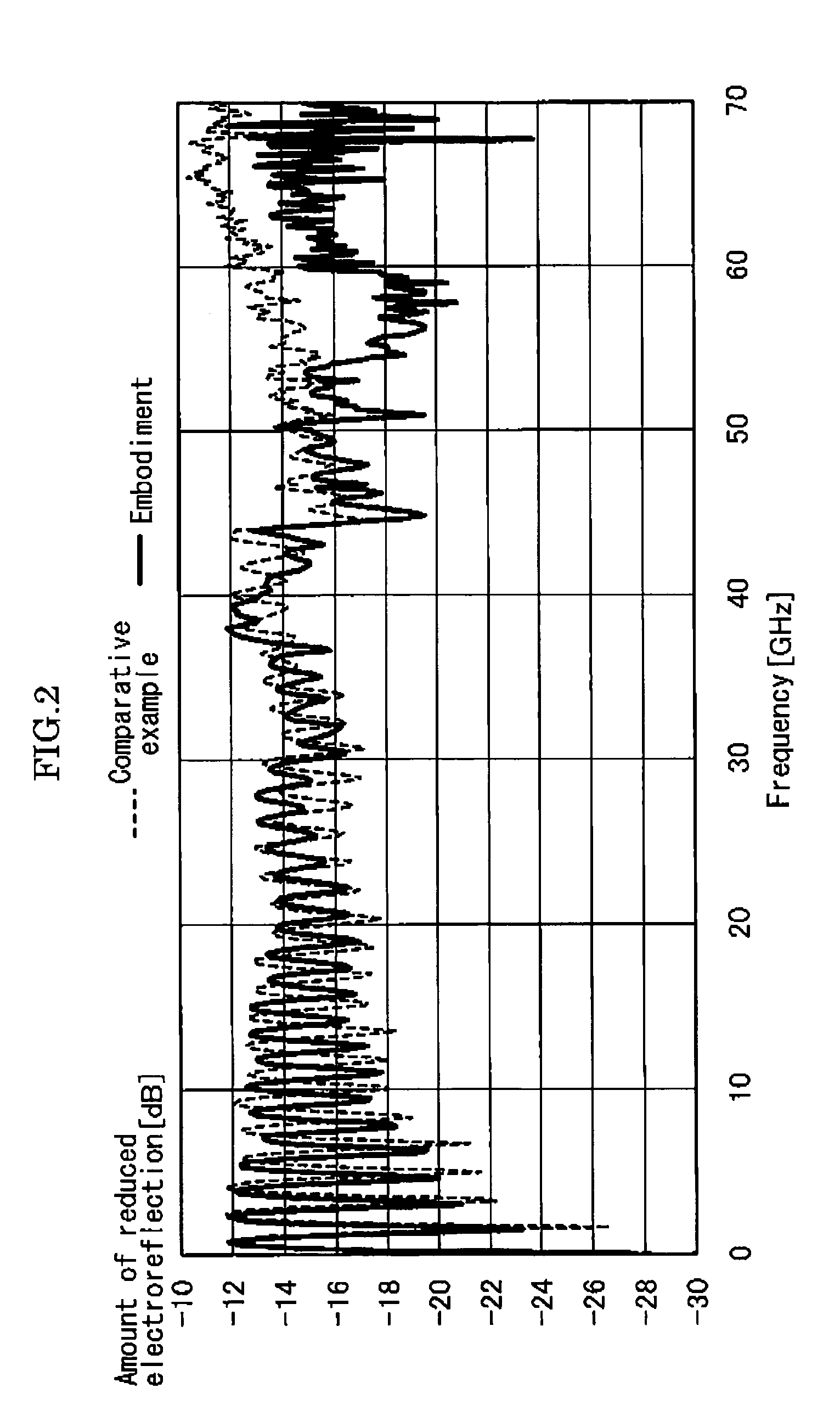
The impedance mismatch causes an electroreflection phenomenon in a high-frequency area, thereby deteriorating the transmittance of the high-frequency signal.
However, in the electrode structure disclosed in Patent Literature 1, the impedance gradually varies and thus it can be expected to reduce the electroreflection phenomenon slightly, but the impedance rapidly varies locally and the electroreflection phenomenon occurs, whereby a satisfactory loss reduction effect cannot be expected.

Method used


Image

  • Light control device
  • Light control device
  • Light control device

Examples


Embodiment Construction

[0029]Hereinafter, a light control device according to an embodiment of the invention will be described in detail.

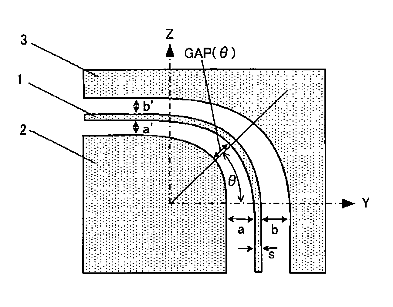
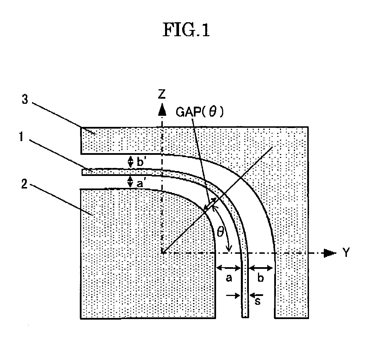
[0030]The light control device according to an embodiment of the invention includes a signal electrode formed on a dielectric anisotropic substrate and ground electrodes disposed with the signal electrode interposed therebetween, the signal electrode includes at least two signal electrode portions disposed in directions in which the dielectric constant of the substrate is different and a curved connecting portion connecting the at least two signal electrode portions, and the connecting portion is configured so that the characteristic impedance in parts connected to the at least two signal electrode portions is equal to that of the corresponding signal electrode portion, and the characteristic impedance in the connecting portion between the at least two signal electrode portions continuously varies.

[0031]To match the characteristic impedance, the material of the signal el...


PUM

PropertyMeasurementUnit
refractive indexaaaaaaaaaa
impedanceaaaaaaaaaa

Abstract

A light control device with a reduced electric loss is provided which can suppress a phenomenon of electrically reflecting a high-frequency signal even when it employs a dielectric anisotropic substrate. A light control device includes a signal electrode formed on a dielectric anisotropic substrate and ground electrodes disposed with the signal electrode interposed therebetween. Here, the signal electrode includes at least two signal electrode portions disposed in directions in which the dielectric constant of the substrate is different from each other and a curved connecting portion connecting the at least two signal electrode portions. The connecting portion is configured so that the characteristic impedance in parts connected to the at least two signal electrode portions is equal to that of the corresponding signal electrode portion, and the characteristic impedance in the connecting portion between the at least two signal electrode portions continuously varies.

Description

CROSS-REFERENCE TO RELATED APPLICATION[0001]The present application claims priority over Japanese Application JP2009-088262 filed on Mar. 31, 2009, the contents of which are hereby incorporated into this application by reference.BACKGROUND OF THE INVENTION[0002]1. Field of the Invention[0003]The present invention relates to a light control device, and more particularly, to a light control device using a dielectric anisotropic substrate.[0004]2. Description of the Related Art[0005]Light control devices in which a signal electrode and a ground electrode are formed on a substrate formed of a dielectric anisotropic material, a high-frequency signal is applied to the signal electrode, and the high-frequency signal is propagated along the signal electrode are generally used. Examples of the light control devices include an optical modulator in which a Mach-Zehnder waveguide having a Y axis as a light-propagating direction is formed in a wafer substrate cut by a plane having the X axis of ...

Claims


Application Information

Patent Timeline
Patent Type & Authority Patents(United States)
IPC IPC(8): G02F1/035G02F1/01G02B6/26G02B6/42
CPCG02F1/035G02F1/295G02F2201/12
Inventor KINPARA, YUHKIICHIOKA, MASAYUKIICHIKAWA, JUNICHIROOIKAWA, SATOSHIISHIKAWA, YASUHIRO
Owner SUMITOMO OSAKA CEMENT CO LTD
Learn More