
Reconfigurable DSP performance in optical transceivers

a technology of optical transceivers and optical transceivers, applied in electromagnetic transmission, electrical equipment, transmission, etc., can solve the problems of complex and costly asics or fpga development, take years of development time, and can cost upwards of $1m to develop, so as to minimize the total power dissipation, reduce the effect of chromatic dispersion compensation function and reduce power dissipation

Active Publication Date: 2013-09-03
ACACIA CHEM
View PDF29 Cites 16 Cited by
  • Summary
  • Abstract
  • Description
  • Claims
  • Application Information

AI Technical Summary

Benefits of technology

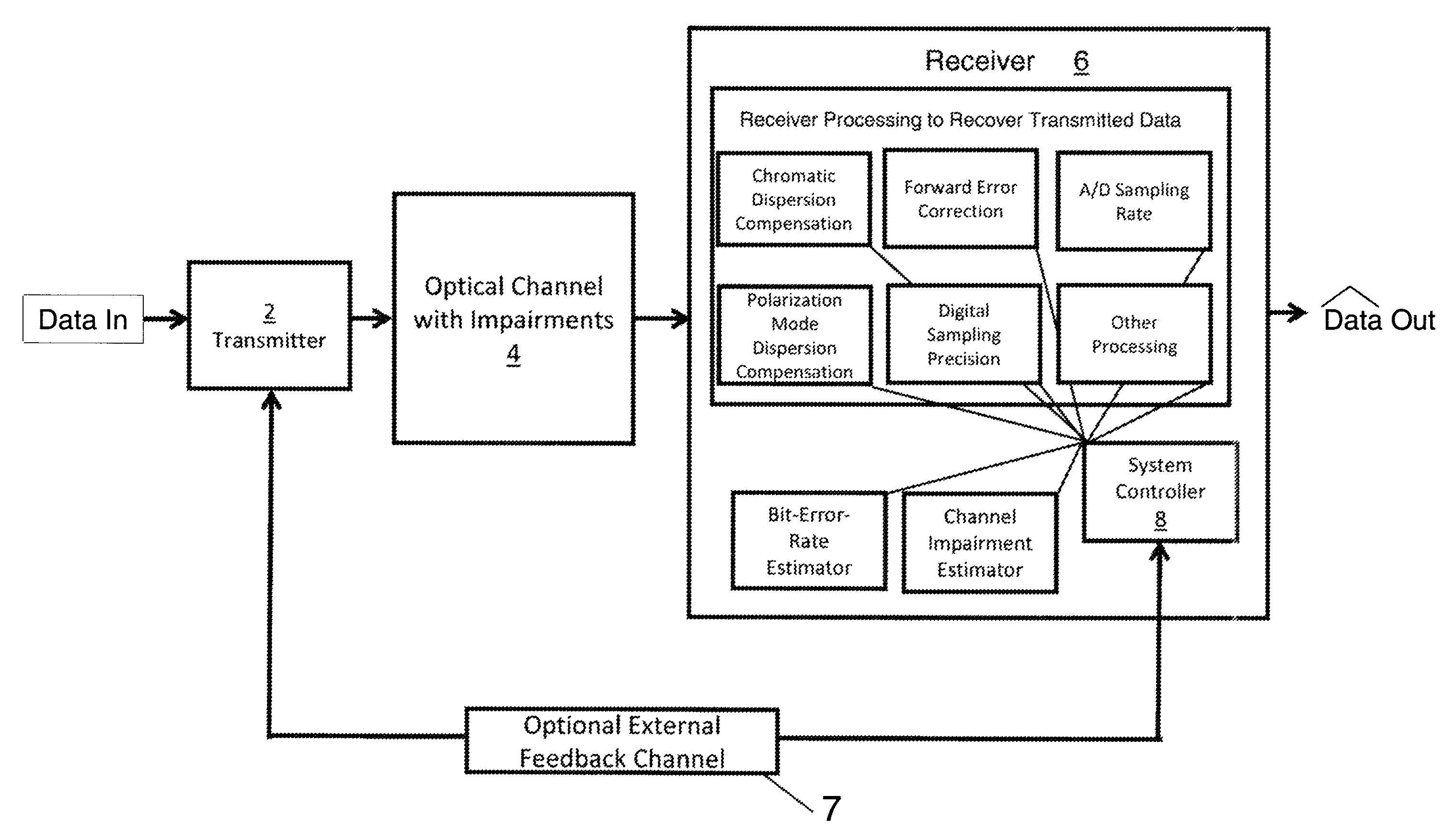
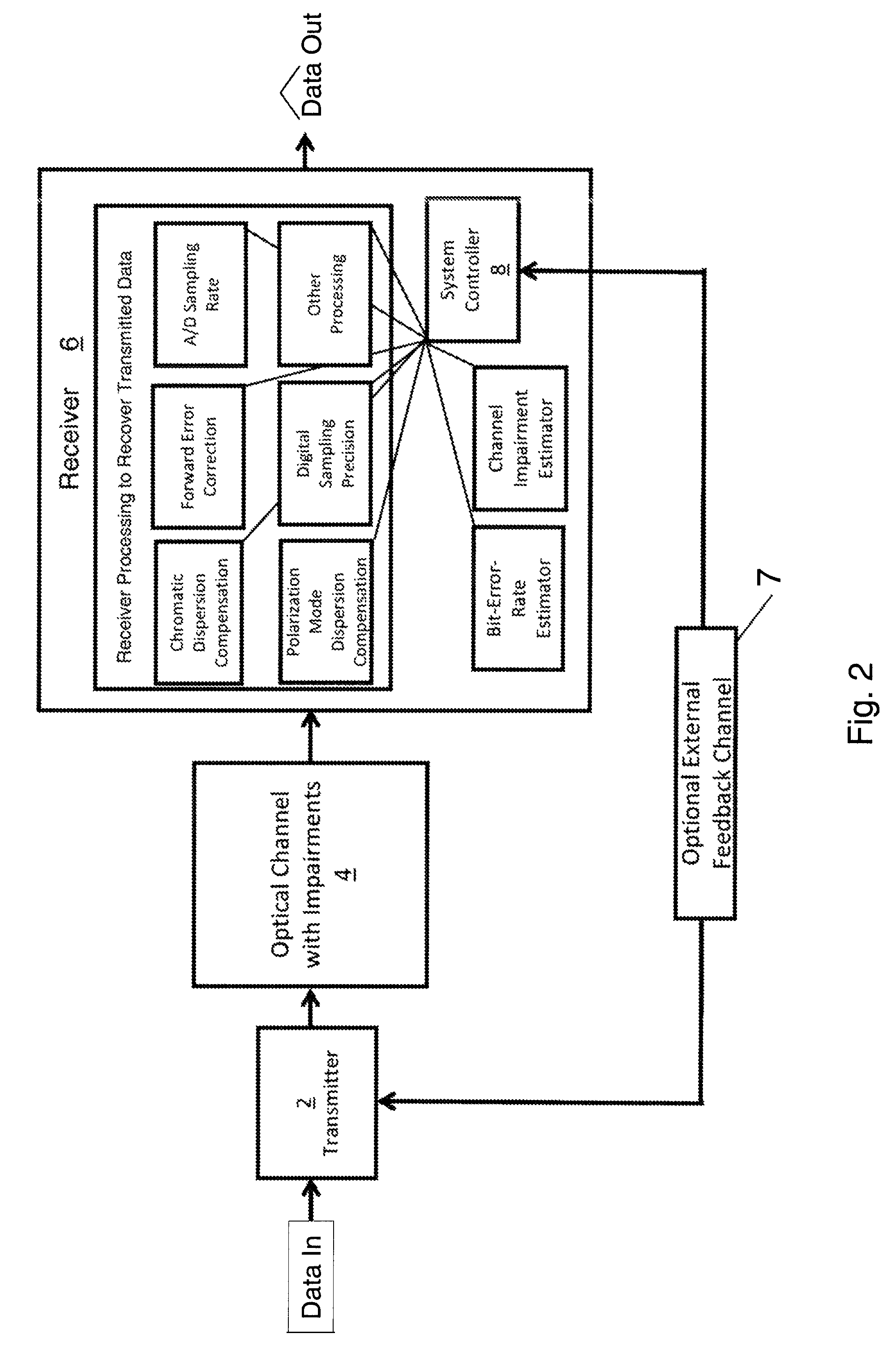
[0010]In one aspect the invention relates to methods for matching transceiver transmission parameters, in a transceiver having a plurality of components, to achieve the predetermined end-to-end bit error rate while reducing power consumption. In one embodiment the method includes the steps of measuring at least one channel parameter necessary to meet the predetermined end-to-end bit error rate; determining which of the plurality of components contribute to the measured channel parameter; and altering the clock, the component parameters and / or the power supplied to components of the transceiver not required to meet the end-to-end bit error rate requirements.
[0012]In another aspect the invention relates to an optical transceiver system that uses digital signal processing to process the data stream sent through a fiber optical channel to modify transmission capabilities to achieve the a predetermined end-to-end bit error rate and to alter its power dissipation to that sufficient to meet said end-to-end bit error rate. In one embodiment the optical transceiver system comprise an optical transmitter; an optical receiver comprising an ASIC; and a controller in electrical communication with the optical receiver, wherein the controller controls clock, component parameters and / or power to portions of the ASIC so as to reduce power dissipation while meeting the end-to-end bit error rate. In another embodiment the clock, component parameters and / or power supplied to the portions of the ASIC is varied in response to either a one-time measurement of at least one channel parameter or a continuous field measurement of at least one channel parameter so as to minimize the total power dissipation while meeting the predetermined end-to-end bit error rate.
[0013]In yet another embodiment portions of the ASIC contain a set of distinct sub-modules for compensating different optical channel impairments. In still yet another embodiment each of the sub-modules are constructed from a plurality of substantially similar blocks that may be powered down individually when not needed to support the said end-to-end bit error rate. In another embodiment a portion of the ASIC is an adaptive equalizer module and the adaptive equalizer module can simultaneously perform both polarization mode dispersion equalization and chromatic dispersion compensation and wherein the chromatic dispersion compensation function may be reduced so as to save power. In another embodiment the adaptive equalizer module includes sub-modules; the sub-modules are continuously monitored for their level of use, and the state of the sub-modules are dynamically changed so as to minimize power consumption.
[0014]In another embodiment power consumption is automatically modified in response to an in-line pseudo-random bit pattern generation, or other continuous or one-time training sequence, during data transmission and subsequent checking on the received data so as to minimize the total power dissipation necessary for the predetermined end-to-end bit error rate. In another embodiment, a PRBS or other training or tracking sequence, code words, or parity check is continuously injected in to part of the output data stream to continuously monitor the received data quality for acceptability while minimizing the power dissipation. In yet another embodiment the ASIC includes an analog to digital converter and the power utilization may be reduced by reducing the sampling rate of the analog to digital converter. In still yet another embodiment the ASIC includes an analog to digital converter and the power utilization can be reduced by reducing the sampling precision of the analog to digital converter.

Problems solved by technology

To design an optical transceiver module often requires the development of a complex and costly ASIC or FPGA.
ASICs can cost upwards of $1M to develop and can take years of development time.
The fact that ASICs are complex and costly to design, and that the requirements for the ASIC can vary depending on the application, leads to conflicts and design tradeoffs.
The latter approach has the advantage of being customized for the deployment scenario but has the disadvantage of requiring much higher development costs plus the disadvantage that the end customer (e.g. a telecommunications carrier) must purchase, install, inventory, and spare a different product for many different deployment scenarios.
The resulting design typically was far from optimal in performance parameters such as power dissipation and other characteristics.

Method used


Image

  • Reconfigurable DSP performance in optical transceivers
  • Reconfigurable DSP performance in optical transceivers
  • Reconfigurable DSP performance in optical transceivers

Examples


Embodiment Construction

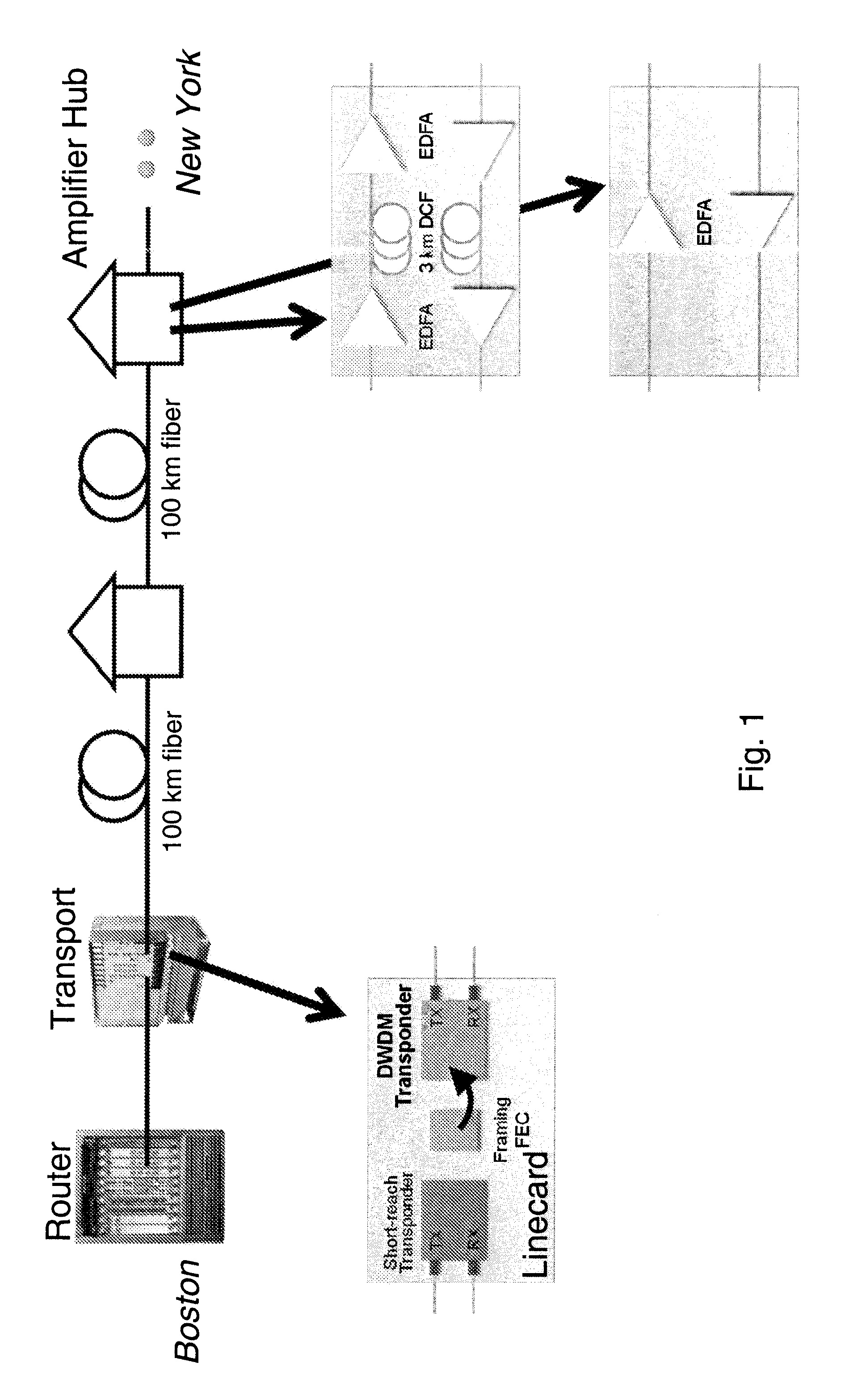
[0025]In brief overview and referring again to FIG. 1, it can be envisioned that there are many installation scenarios of interest to system vendors and their end customers who are telecommunication companies, cable operators, and data centers, government organizations, etc. There are several metrics that help define the installation scenario with respect to the needs of the optical transceiver system. This includes: 1) the transmission distance which is often loosely described as LAN, metro, regional, long-haul, and ultra-long-haul applications; 2) the fiber type standard SMF (single mode fiber), zero-dispersion fiber, dispersion shifted fiber, and other types of fiber; 3) the dates on which the fiber was manufactured and how it was installed; and 4) the characteristics of how the optically amplified link is designed (e.g. with amplifier huts and with or without dispersion compensation at each amplifier hut). It is these and other widely varying characteristics—total transmission d...


PUM


Abstract

A method for setting transceiver transmission parameters, in a transceiver having a plurality of components, to achieve the predetermined acceptable end-to-end bit error rate while reducing power consumption. In another aspect the invention relates to an optical transceiver system that uses digital signal processing to process the data stream sent through a fiber optical channel to compensate for transmission, reception and channel impairments to achieve the a predetermined end-to-end bit error rate and to alter its power dissipation to that sufficient to meet said end-to-end bit error rate. In one embodiment the optical transceiver system includes an optical transmitter; an optical receiver comprising an ASIC, FPGA, or other circuitry; and a controller in electrical communication with the optical receiver, wherein the controller controls power to portions of the ASIC so as to reduce power dissipation while meeting the end-to-end bit error rate.

Description

FIELD OF INVENTION[0001]This invention relates generally to the field of optical transceivers used in optical transmission systems, and more particularly to fiber optic transmission systems that use digital signal process (DSP) techniques to improve the sensitivity, transmission distance, and transmission capacity and compensate for channel impairments.BACKGROUND OF THE INVENTION[0002]There will be an emergence of digital signal processing (DSP) based optical transceivers for use in optical transmission systems. Such DSP based transceivers offer great advantages over traditional approaches; this includes: lower costs; smaller size; and increased sensitivity, increased transmission distance, increased transmission capacity, and simpler design, installation, turn-up, and maintenance.[0003]DSP based transceivers can be direct detection or coherent detection based. Direct detection systems come in a variety of modulation formats and include On / Off Keying, Differential Phase Shift Keying...

Claims


Application Information

Patent Timeline
Patent Type & Authority Patents(United States)
IPC IPC(8): H04B10/00
CPCH04B10/0795
Inventor SWANSON, ERICPENDOCK, GRAEME JOHNSHAH, BHUPENDRAPELLACH, LAWRENCE S.
Owner ACACIA CHEM
Learn More