Dual-mode counter-rotating-to-traditional electric motor and system

a technology of electric motors and counter-rotating brushes, applied in the direction of electric devices, cycle equipment, optical signals, etc., can solve the problems of difficult fabrication, high manufacturing cost, and limited operation life of such motors

Active Publication Date: 2013-09-10
E WISH TECH
View PDF22 Cites 29 Cited by
  • Summary
  • Abstract
  • Description
  • Claims
  • Application Information

AI Technical Summary

Problems solved by technology

Clearly, the operational lifetime of such a motor is extremely limited, given its destruction upon hitting a target.
This radial commutator / brush design is complex, not easily fabricated, and, thus, expensive to manufacture.
When counter-rotation of motor components is part of the operation of the device the means for electrical communication is critically important and extremely difficult to achieve.
Unfortunately, the manner in which the device receives or delivers electricity is not related, nor are any internal electrical components described.
Clearly, due to the difficulty of actually operating their multi-brush / slip ring motor, much of the presented / plotted data is not actual physical collected data for a twin-rotor motor but “estimated” data from “equivalent” situations.
This issued patent is, literally, filled with dozens of major errors, including: inconsistent statements; wrong / inappropriate equations; incorrectly and incompletely drawn figures; elements listed as being in the figures and not actually presented in the figures; and mechanically / electrically impossible configurations for the theoretical motor.
Further, the “Formulas Refresher” table presents a somewhat unrelated group of equations that are, mostly, utilized for linear motion and not appropriate in an analysis of rotational motion.
Unfortunately, this patent was allowed to issue with all of the gross errors, untrue statements, and incorrect analysis.

Method used


Image

  • Dual-mode counter-rotating-to-traditional electric motor and system
  • Dual-mode counter-rotating-to-traditional electric motor and system
  • Dual-mode counter-rotating-to-traditional electric motor and system

Examples


Embodiment Construction

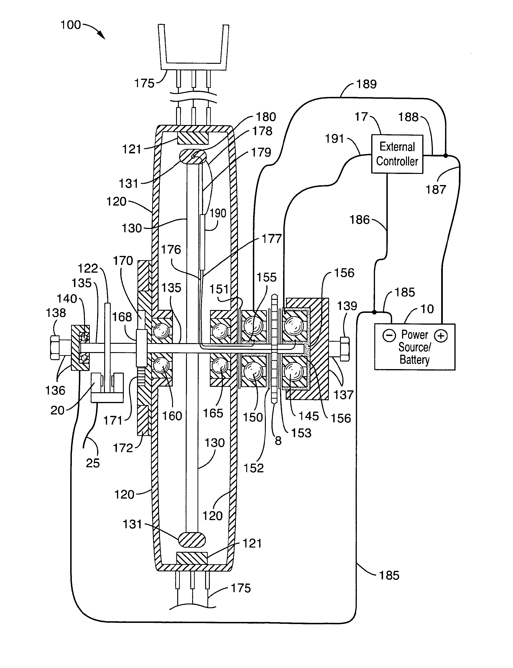
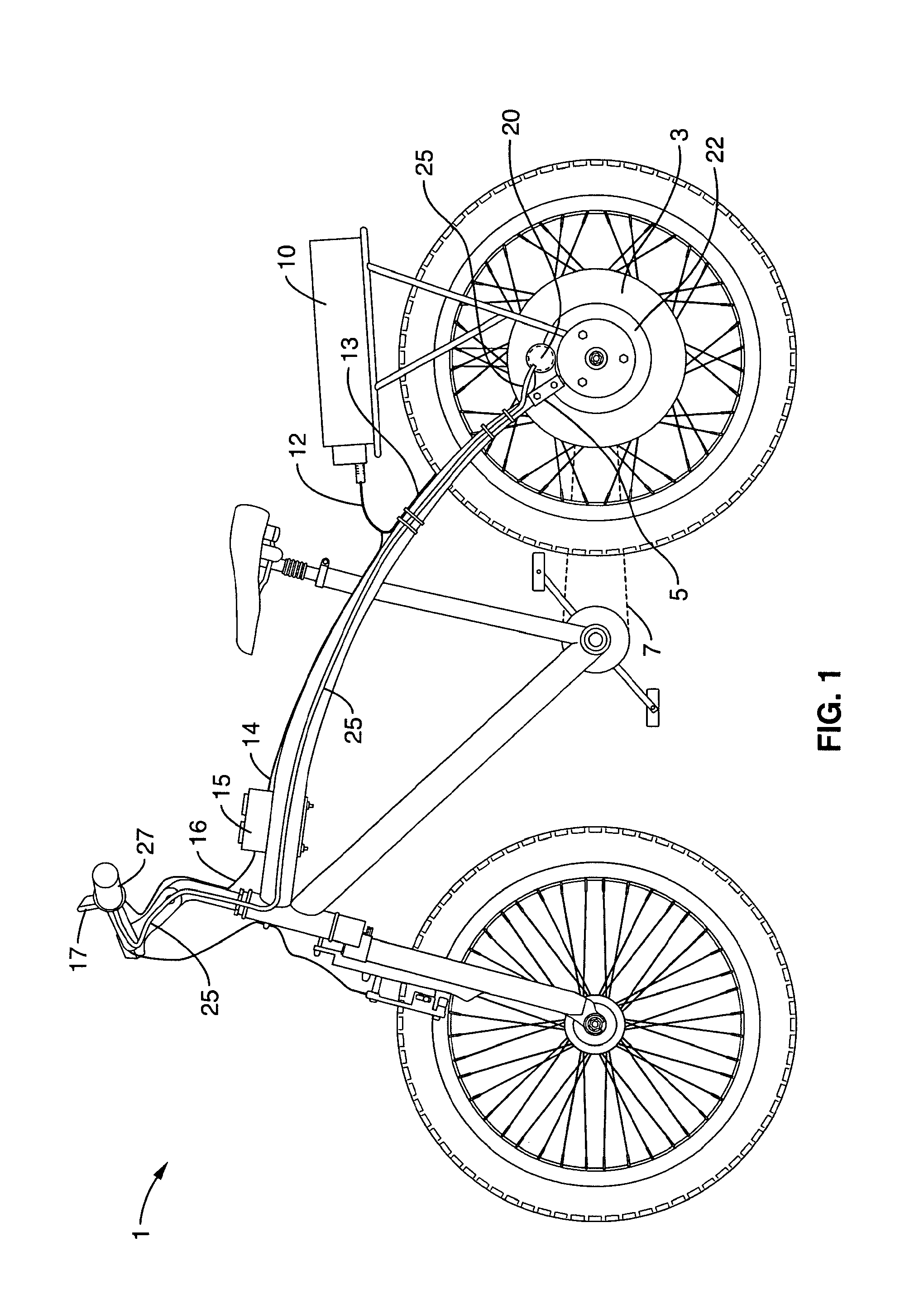
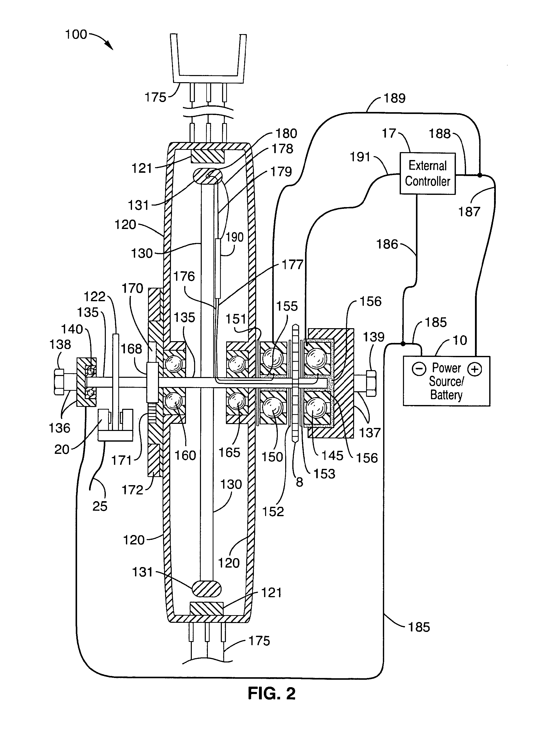
[0038]Referring more specifically to the drawings, for illustrative purposes the present invention is presented in the embodiments generally shown in FIGS. 1 through 4. It will be appreciated that the subject invention may vary as to configuration and as to details of the parts without departing from the basic concepts as disclosed herein.

[0039]The subject invention comprises a counter-rotating motor that operates in a dual-mode fashion in which, upon the choice of a user or via suitable programming, the counter-rotating motor, with its oppositely rotating outer and inner rotational members, switches to a traditional motor in which only one rotational member rotates. The benefit of this dual-mode operation is that a motor's efficiency varies with many factors, including the relative rotational motion between the stator (outer rotational member) and the armature (inner rotational member). For a traditional motor only the armature spins and the stator in fixed and the overall motor ou...


PUM


Abstract

Disclosed is a counter-rotating electric motor that includes an outer rotational component, an oppositely rotating inner rotational component, a force output system coupled to the outer rotational component, another force output means coupled to the inner rotational component, and an assembly for reversibly halting one of the rotational components, thereby converting the counter-rotating electric motor into a traditional motor.

Description

CROSS-REFERENCE TO RELATED APPLICATIONS[0001]This application claims priority from U.S. provisional application Ser. No. 61 / 463,364 filed on Feb. 16, 2011.BACKGROUND OF THE INVENTION[0002]1. Field of the Invention[0003]The subject invention relates to an increased efficiency counter-rotating electric motor that, upon demand, converts into a traditional electric motor, thereby producing a device that operates in efficient power output ranges at both slow rpm and high rpm circumstances. Specifically, the subject invention utilizes a counter-rotating electric motor in which both an armature or inner rotational member and a stator or outer rotational member rotate in opposite directions during operation. Generally, the subject motor is configured as a separate motor (that may be mounted in a vast variety of motor-containing systems as desired) with two oppositely rotating output drives or for a vehicle is mounted at the center of one wheel (hub motor) of the selected wheeled vehicle, wh...

Claims


Application Information

Patent Timeline
Patent Type & Authority Patents(United States)
IPC IPC(8): H02K23/60
CPCB62M6/45B62M6/65H02K7/116H02K16/005B62K5/027B60L11/007B60L2200/12Y02T10/641B60L2220/44B60L2270/40H02K21/22B60L50/20Y02T10/64
Inventor WISHART, RANDELL J.
Owner E WISH TECH
Why Eureka
Try Eureka