Digital hold in a phase-locked loop

a phase-locked loop and digital hold technology, applied in the direction of generating/distributing signals, instruments, pulse techniques, etc., can solve the problems of not meeting the clock signal generated in holdover mode may still drift, and certain plls may fail to meet the requirements of holdover

Active Publication Date: 2013-09-10
SKYWORKS SOLUTIONS INC
View PDF12 Cites 6 Cited by
  • Summary
  • Abstract
  • Description
  • Claims
  • Application Information

AI Technical Summary

Problems solved by technology

However, the clock signal generated in holdover mode may still drift to such an extent as to fail to meet the holdover requirements.
For example, certain PLLs may fail to meet holdover requirements because the voltage controlled oscillators utilized in such systems have too much frequency variation over temperature (e.g., 100 ppm / ° C.).
In addition, certain phase-locked loops, for example, phase-locked loops using digital techniques as described in application Ser. No. 09 / 902,541, filed Jul. 10, 2001, entitled “Digitally-Synthesized Loop Filter Circuit Particularly Useful for a Phase-Locked Loop”, fail to meet the initial accuracy required when first entering holdover mode due to truncation error.

Method used


Image

  • Digital hold in a phase-locked loop
  • Digital hold in a phase-locked loop
  • Digital hold in a phase-locked loop

Examples


Embodiment Construction

)

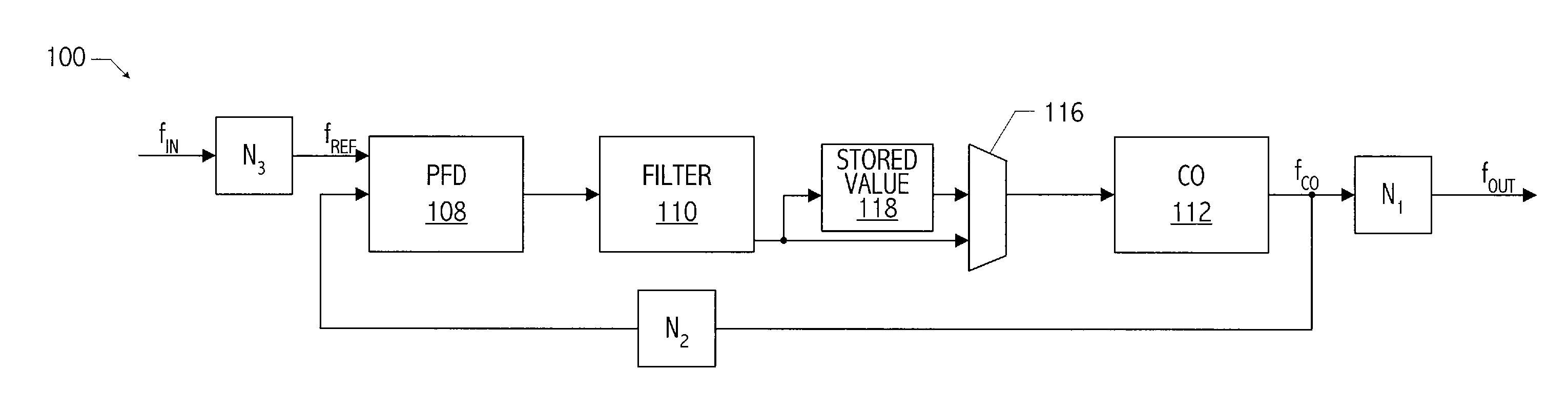
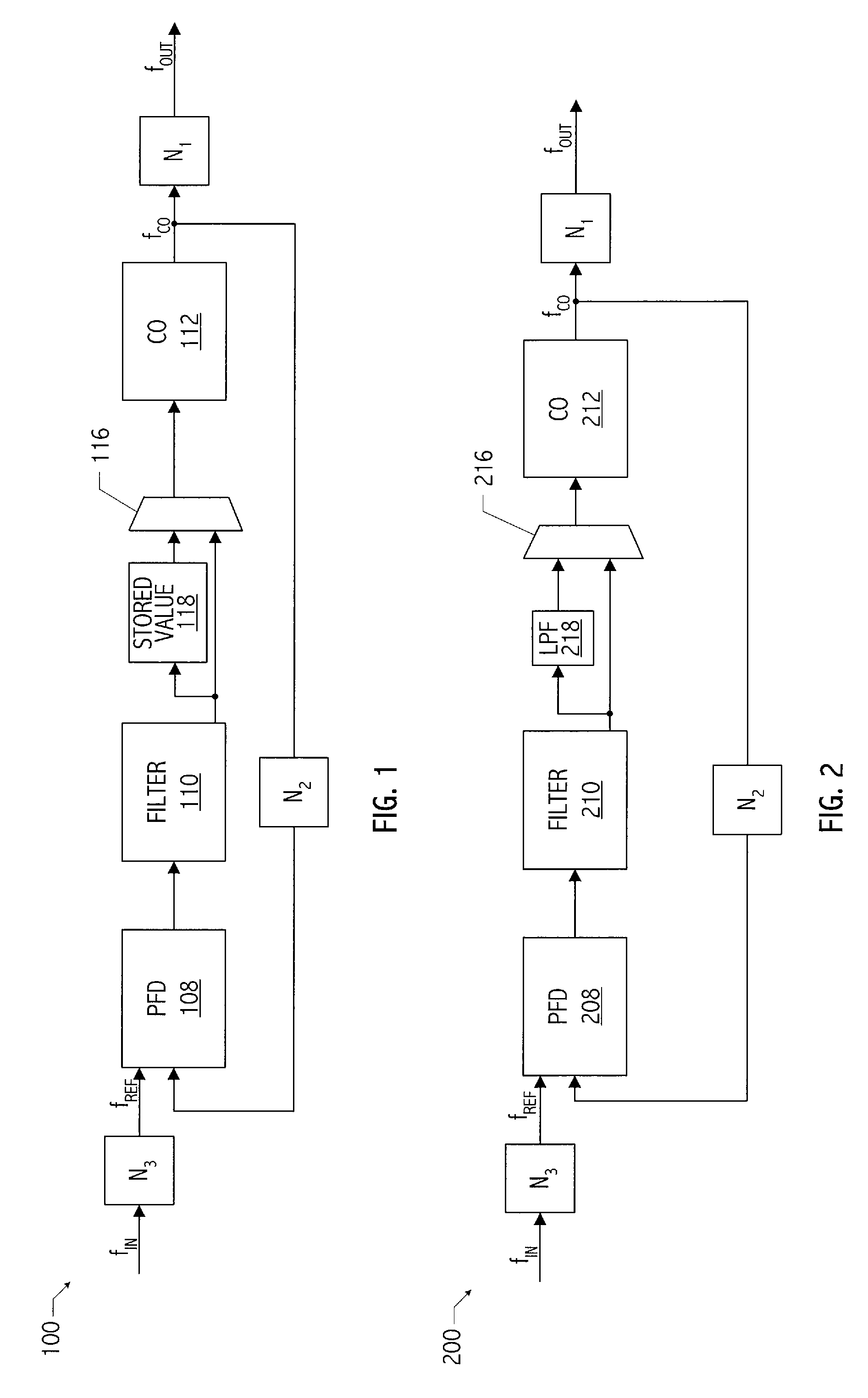
[0020]Referring to FIG. 1, an exemplary phase-locked loop (i.e., PLL 100) architecture has a programmable bandwidth (i.e., f3 dB) and a programmable reference frequency (i.e., fREF). Such features of a PLL architecture are described in provisional application No. 60 / 827,530, filed Sep. 29, 2006, entitled “Hitless Switching Architecture,” naming Srisai R. Seethamraju, Ronald B. Hulfachor, and Shailesh Chitnis as inventors, which application is incorporated herein by reference. Note that features of PLL 100 are exemplary only and the invention disclosed herein may be implemented in other PLL architectures.

[0021]When a holdover condition occurs in PLL 100, that is, when reference clock signal fREF fails, which may be indicated by a loss of signal condition indicator, loop filter 110 of PLL 100 is “frozen” such that a digital control value used to drive controllable oscillator 112 no longer tracks changes to the reference signal, and the frozen output of the loop filter (e.g., stored v...


PUM


Abstract

A technique that is readily implemented in monolithic integrated circuits includes a method including generating an output clock signal during a presence of a reference clock signal based, at least in part, on a digital control value indicating a phase difference between a feedback signal of a PLL and a reference clock signal. The method includes generating the output clock signal during an absence of the reference clock signal and based, at least in part, on an average digital control word indicating an average value of a number of samples of the digital control value during the presence of the reference clock signal, the number of samples preceding the absence of the reference clock signal by a delay period. The number of samples is selected from a plurality of numbers of samples and the delay period is selected from a plurality of delay periods.

Description

BACKGROUND[0001]1. Field of the Invention[0002]This application relates to clock signal generation in high speed systems and more particularly to generation of clock signals when a reference signal used in generating those clock signals is lost.[0003]2. Description of the Related Art[0004]High speed communication systems require high speed clock signals for transmission and reception of information. For example, in optical communication systems, line cards compliant with standards such as Synchronous Optical Network (SONET) or Synchronous Digital Hierarchy (SDH) (the European counterpart to SONET), utilize clock generation circuits to generate high speed clock signals used in data transmission and reception. In a typical clock generation circuit in such SONET (or SDH) compliant systems, a phase-locked loop (PLL) receives a synchronization input reference clock signal and generates one or more high speed clock signals suitable for use in transmitting or receiving data. According to o...

Claims


Application Information

Patent Timeline
Patent Type & Authority Patents(United States)
IPC IPC(8): H03D3/24
CPCG06F1/04H03L7/146H03L7/148H03L7/18
Inventor SEETHAMRAJU, SRISAI R.HEIN, JERRELL P.WONG, KENNETH KIN WAIYU, QICHENG
Owner SKYWORKS SOLUTIONS INC
Why Eureka
Try Eureka