Blood pump with expandable cannula

a blood pump and expandable technology, applied in the field of blood pumps, can solve the problems of increasing the stress of heart failure patients, impractical or impossible to percutaneously insert a pump of the size needed for sustaining adequate blood flow, and claiming many lives per year, so as to facilitate the collapse of the expandable portion, reduce the risk of blood pooling, and maintain the effect of cross-section

Active Publication Date: 2013-09-17
TC1 LLC +1
View PDF336 Cites 121 Cited by
  • Summary
  • Abstract
  • Description
  • Claims
  • Application Information

AI Technical Summary

Benefits of technology

[0008]The operation of the aforementioned percutaneous blood pumps have faced several challenges, including the leakage of blood through a guide wire lumen extending through the pump impeller, maintaining the blood pump impeller centered within the outer cannula as the cannula bends within the vascular system, retracting the blood pump into the insertion sheath for removal from the human body, and designing and maintaining the shape of the expandable portion of the cannula of the blood pump to optimize performance.
[0023]Another embodiment described herein is directed to a method of collapsing an expandable pump. This method can be used, for example, for preparing a percutaneous blood pump for insertion into a patient. This method can include providing a percutaneous blood pump that can include an expandable distal portion having a proximal end, a distal end, a tubular matrix extending between the proximal and distal ends, an impeller disposed within the duct between the proximal and distal ends, and a sheath. In some embodiments, the sheath can have a generally non-expanding distal portion. For example, the sheath can be configured to have a substantially constant cross-section in the absence of a radially outwardly directed force. In some arrangements involving funnel-less deployment and retraction, there can be some deformation of the sheath while still achieving the benefits of minimizing potential pooling of blood. This method can also include providing relative motion between the distal portion of the sheath and the proximal end of expandable portion such that the distal portion of the retainer sheath applies a radially inward force to induce radial collapse of a distal region of the tubular matrix to facilitate collapse of the expandable portion into the sheath.

Problems solved by technology

Heart disease is a major problem in society, and claims many lives per year.
Surgical placement is required, since it is presently impractical or impossible to percutaneously insert a pump of the size needed for sustaining adequate blood flow.
Surgical insertion, however, can cause additional serious stresses in heart failure patients.

Method used


Image

  • Blood pump with expandable cannula
  • Blood pump with expandable cannula
  • Blood pump with expandable cannula

Examples


Embodiment Construction

I. Apparatus

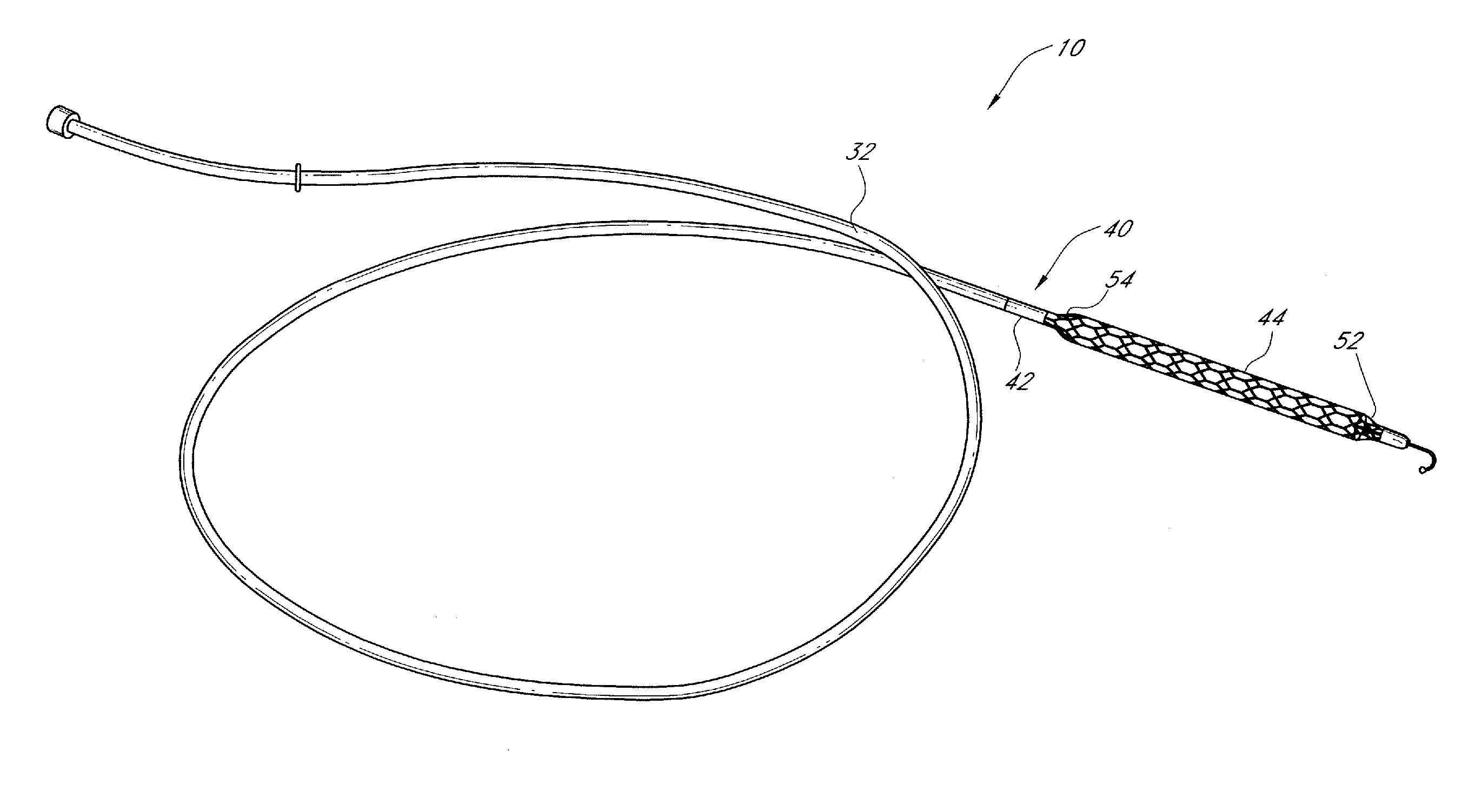
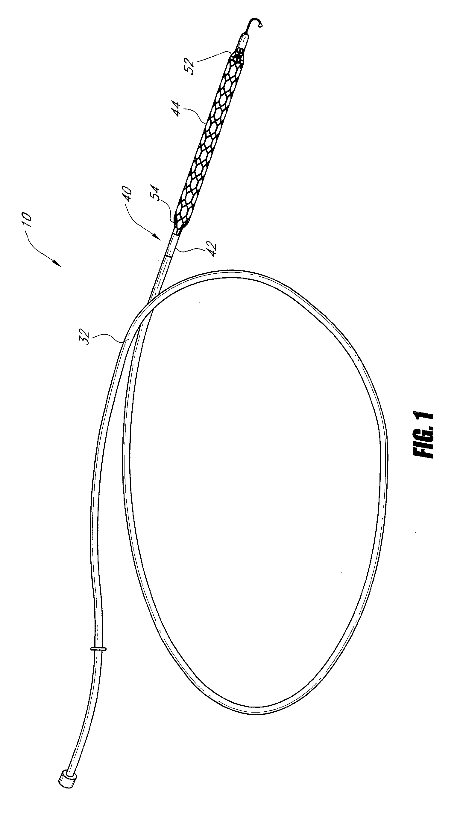
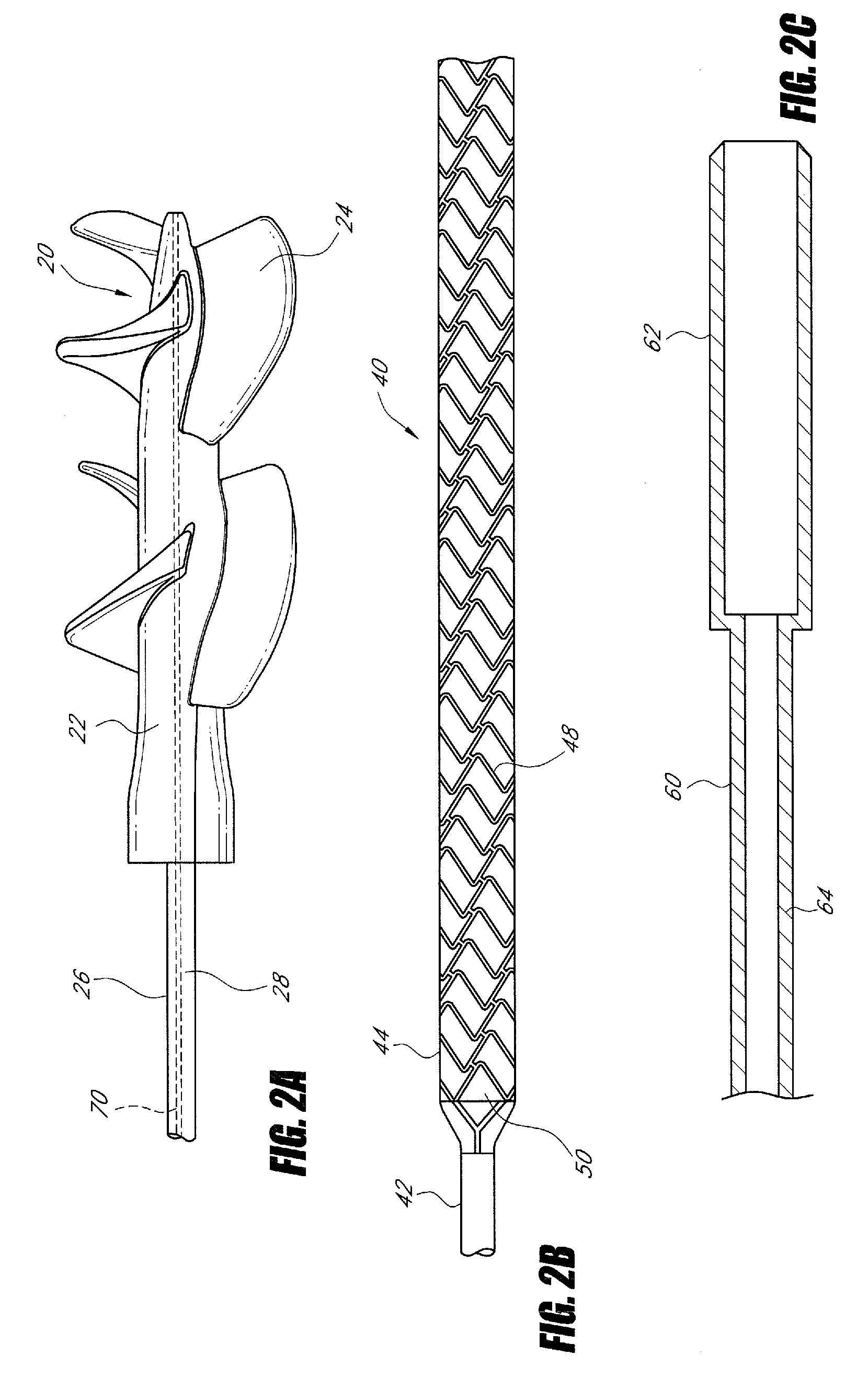
[0058]A blood pump 10 according to the present invention has various applications within the human body, including as a left ventricle assist device, as a right ventricle assist device, for supplementing blood flow to organs, and the like. Referring to FIGS. 1 and 2A-C, blood pump 10 can include three main components, a rotatable impeller 20; a cannula 40 in which the impeller 20 resides; and a retainer sheath 60 overlying the cannula 40. Although each of these parts will be described generally below, blood pump 10 can include any or all of the structural arrangements and features described in U.S. Pat. No. 7,841,976 the disclosure of which is hereby incorporated by reference herein.

A. Impeller

[0059]Impeller 20 includes a hub 22 and a plurality of blades 24. Blades 24 can be foldable against hub 22 so as to reduce the cross-sectional size of impeller 20 for percutaneous insertion into the body. Once impeller 20 has been located in a desired position, blades 24 can be exp...


PUM


Abstract

A blood pump includes an impeller having a plurality of foldable blades and a cannula having a proximal portion with a fixed diameter, and a distal portion with an expandable diameter. The impeller can reside in the expandable portion of the cannula. The cannula has a collapsed condition for percutaneous delivery to a desired location within the body, and an expanded condition in which the impeller can rotate to pump blood. A flexible drive shaft can extend through the cannula for rotationally driving the impeller within the patient's body.

Description

CROSS-REFERENCE TO RELATED APPLICATIONS[0001]This application claims priority to U.S. Provisional Patent Application Ser. No. 61 / 222,236, filed Jul. 1, 2009, which is incorporated herein by reference in its entirety for all purposes.BACKGROUND OF THE INVENTION[0002]1. Field of the Invention[0003]This application relates to blood pumps such as left or right ventricular assist devices with an expandable impeller for treatment of heart disease. Still more particularly, this application relates to expandable cannulas for use in such blood pumps, and to other structural features of these devices.[0004]2. Description of the Related Art[0005]Heart disease is a major problem in society, and claims many lives per year. After a heart attack, only a small number of patients can be treated successfully and non-invasively using medicines, such as pharmaceuticals. However, with sufficient mechanical assistance to the heart function, a majority of patients may recover from a heart attack, includin...

Claims


Application Information

Patent Timeline
Patent Type & Authority Patents(United States)
IPC IPC(8): A61N2/00A61N1/00
CPCA61M60/857A61M60/414A61M60/808A61M60/422A61M60/237A61M60/894A61M60/139A61M60/148A61M60/13
Inventor CAMPBELL, ROBERT L.WALSH, JUSTIN M.METREY, DANIELKUNZ, ROBERT F.MALLISON, THOMAS M.BOONE, EDWARDMYER, ERICMCBRIDE, MARK W.POWELL, KEVIN J.WALTERS, DANIEL A.
Owner TC1 LLC
Why Eureka
Try Eureka