Electrochemical device

a technology of electrochemical devices and electrodes, which is applied in the direction of coupling device connections, electrical apparatus casings/cabinets/drawers, sustainable manufacturing/processing, etc., can solve the problems of electrolyte vapor pressure rise, leakage out of sealed parts, and inability to meet the demand for electrochemical devices

Inactive Publication Date: 2013-09-17
TAIYO YUDEN KK
View PDF22 Cites 18 Cited by
  • Summary
  • Abstract
  • Description
  • Claims
  • Application Information

AI Technical Summary

Benefits of technology

[0013]According to the present invention, there is provided an electrochemical device compatible with high-temperature reflow soldering using a lead-free solder.
[0014]The foregoing object and the other objects of the present invention, a constituent feature thereof, and an operation and advantage thereof will be apparent with a description to be made below and appended drawings.

Problems solved by technology

However, because the aforesaid electrochemical device is not compatible with high-temperature reflow soldering using a lead-free solder, demand for an electrochemical device that can be, similarly to a general electronic component, mounted on a substrate or the like by high-temperature reflow soldering using a lead-free solder cannot be met.
A disadvantage occurs in that, due to heat, the electrolyte undergoes a vapor pressure rise and leaks out of the sealed part.Patent document 1: Japanese Patent Laid-open No.-2006-210201

Method used


Image

  • Electrochemical device
  • Electrochemical device
  • Electrochemical device

Examples


first embodiment

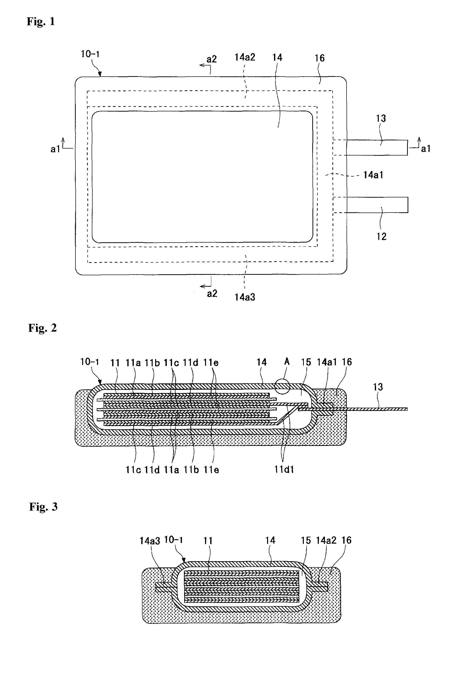
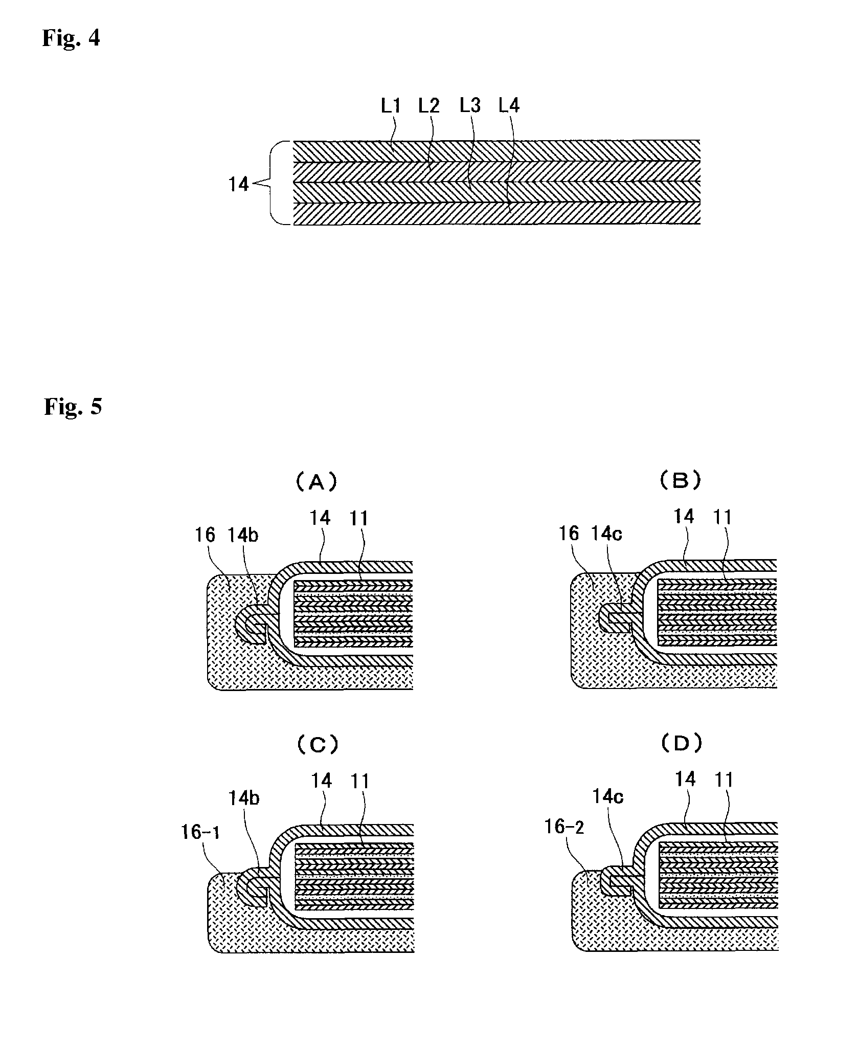
[0059]FIG. 1 to FIG. 4 show a first embodiment in which the present invention is applied to an electrical double layer capacitor. FIG. 1 is a top view of the electrical double layer capacitor, FIG. 2 is a longitudinal sectional view along an a1-a1 line in FIG. 1, FIG. 3 is a longitudinal sectional view along an a2-a2 line in FIG. 1, and FIG. 4 is a detail view of a part A of FIG. 2.

[0060]An electrical double layer capacitor 10-1 of the first embodiment includes an electric storage element 11, a pair of terminals (a positive-electrode terminal 12 and a negative-electrode terminal 13), a package 14, an electrolyte 15, and a support 16.

[0061]The electric storage element 11 is formed by alternately stacking a positive electrode (no reference number) and a negative electrode (no reference number) with a separator 11e between them. The positive electrode includes a polarized electrode for positive electrode 11a and a positive current collector 11b superimposed on the polarized electrode f...

second embodiment

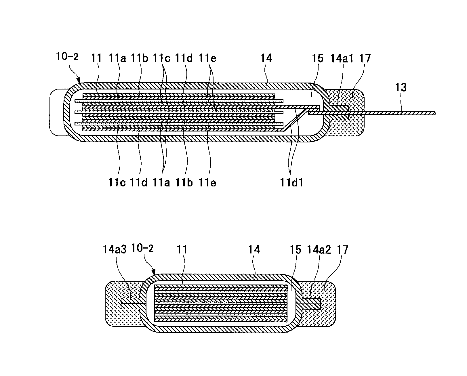
[0082]FIG. 6 to FIG. 8 show a second embodiment in which the present invention is applied to an electrical double layer capacitor. FIG. 6 is a top view of the electrical double layer capacitor, FIG. 7 is a longitudinal sectional view along a b1-b1 line in FIG. 6, and FIG. 8 is a longitudinal sectional view along a b2-b2 line in FIG. 6.

[0083]An electrical double layer capacitor 10-2 of the second embodiment is different from the construction of the electrical double layer capacitor 10-1 of the first embodiment in the overall shape of a support 17. Because the other components are identical to those of the electrical double layer capacitor 10-1 of the first embodiment, the same reference numerals are cited, and the description is omitted.

[0084]The support 17 is formed using the same material as the support 16 of the electrical double layer capacitor 10-1 of the first embodiment so that it can continuously cover solely the sealed parts 14a1 to 14a3 of the package 14. The support 17 has...

third embodiment

[0096]FIG. 10 to FIG. 12 show a third embodiment in which the present invention is applied to an electrical double layer capacitor. FIG. 10 is a top view of the electrical double-layer capacitor, FIG. 11 is a longitudinal sectional view along a c1-c1 line in FIG. 10, and FIG. 12 is a longitudinal sectional view along a c2-c2 line in FIG. 10.

[0097]An electrical double layer capacitor 10-3 of the second embodiment is different from the construction of the electrical double layer capacitor 10-1 of the first embodiment in the overall shape of a package 18 and the overall shape of a support 19. Because the other components are identical to those of the electrical double layer capacitor 10-1 of the first embodiment, the same reference numerals are cited and the description is omitted.

[0098]The package 18 is formed using the same film as the package 14 of the electrical double layer capacitor 10-1 of the first embodiment is so that the contour thereof becomes rectangular. The package 18 ha...


PUM

PropertyMeasurementUnit
furnace temperatureaaaaaaaaaa
temperatureaaaaaaaaaa
rigidityaaaaaaaaaa

Abstract

Provided is an electrochemical device compatible with high-temperature reflow soldering using a lead-free solder. An electrical double layer capacitor 10-1 includes a package 14 that is constructed with a film or films and has sealed parts 14a1 to 14a3 formed by sealing parts, in which films are superimposed on each other, by, for example, heat sealing. The entireties of the sealed parts 14a1 to 14a3 of the package 14 are covered in a close-contact state with a support 16 that has higher rigidity than the film(s) constructing the package 14.

Description

[0001]This application is the U.S. National Phase under 35 U.S.C. §371 of International Application PCT / JP2009 / 055566, filed Mar. 16, 2009, which claims priority to Japanese Patent Application No. 2008-69316, filed Mar. 18, 2008. The International Application was published under PCT Article 21(2) in a language other than English.TECHNICAL FIELD[0002]The present invention relates to an electrochemical device provided with a package in which an electric storage element is enclosed.BACKGROUND ART[0003]Electrochemical devices, for example, an electrical double layer capacitor, a lithium ion capacitor, a redox capacitor, and a lithium ion battery include those provided with a package having a sealed part formed by sealing portions of the film(s) superimposed on each other.[0004]For example, the foregoing electrical double layer capacitor has a structure in which an electric storage element formed by sequentially stacking a positive electrode and a negative electrode with a separator betw...

Claims


Application Information

Patent Timeline
Patent Type & Authority Patents(United States)
IPC IPC(8): H01R13/46H01G9/22H01G11/00H01G11/10H01G11/12H01G11/78H01G11/82H01M50/103
CPCH01G2/10H01G9/10H01G9/155Y02E60/13H01M2/0202Y02E60/10Y02P70/50H01G11/78H01G11/82H01G11/76H01M50/103
Inventor HAGIWARA, NAOTOISHIDA, KATSUEIYAWATA, KAZUSHIKOBAYASHI, MOTOKI
Owner TAIYO YUDEN KK
Why Eureka
Try Eureka