Biopsy and sutureless device

a technology of tissue extraction and suture, which is applied in the field of tissue extraction, can solve the problems of needle stick injury, increased cost of suture and sterilization of instruments, etc., and achieve the effect of reducing time and effor

Inactive Publication Date: 2013-09-24
MENDEZ COLL JOSE ARTURO
View PDF11 Cites 431 Cited by
  • Summary
  • Abstract
  • Description
  • Claims
  • Application Information

AI Technical Summary

Benefits of technology

[0011]The first embodiment of the biopsy punch device comprises an elongated hollow cylinder with a distal end having an exposed cylindrical cutter which rotates during the incision procedure and is then retracted into the body of the elongated hollow cylinder while the cylindrical cutter assists with the grasping and removing of the tissue sample and; wherein said cylindrical cutter is coupled to a sutureless fastening mechanism. The sutureless fastening mechanism comprises a sutureless dispenser to dispense a biopsy closure fastener member. The sutureless biopsy closure dispenser releases the biopsy closure fastener member at the wound site which renders the biopsy wound site closed by approximating the opposing edges of the wound. The biopsy closure fastener member comprises a two-pronged fastener having resilient properties, wherein the two-pronged fastener may expand to a distance at least equal to the diameter of the wound created by the cylindrical cutter and then contracts when released therein. The present biopsy punch device eliminates the need for multiple instruments and their handling, sutures and speeds-up the process.
[0013]It is a further objective to provide a biopsy punch cutter blade that is inexpensive to manufacture such that it can be made disposable.
[0016]Another objective is to minimize time and effort during the process of closing the wound site.

Problems solved by technology

Some of the problems associated with this technique include, but are not limited to, the use of multiple instruments in performing the suturing which typically requires at least a needle holder, scissors, suture material and forceps.
Other problems are the potential for a needle stick injury and the increased cost of the suture and sterilization of the instruments used.

Method used


Image

  • Biopsy and sutureless device
  • Biopsy and sutureless device
  • Biopsy and sutureless device

Examples


Embodiment Construction

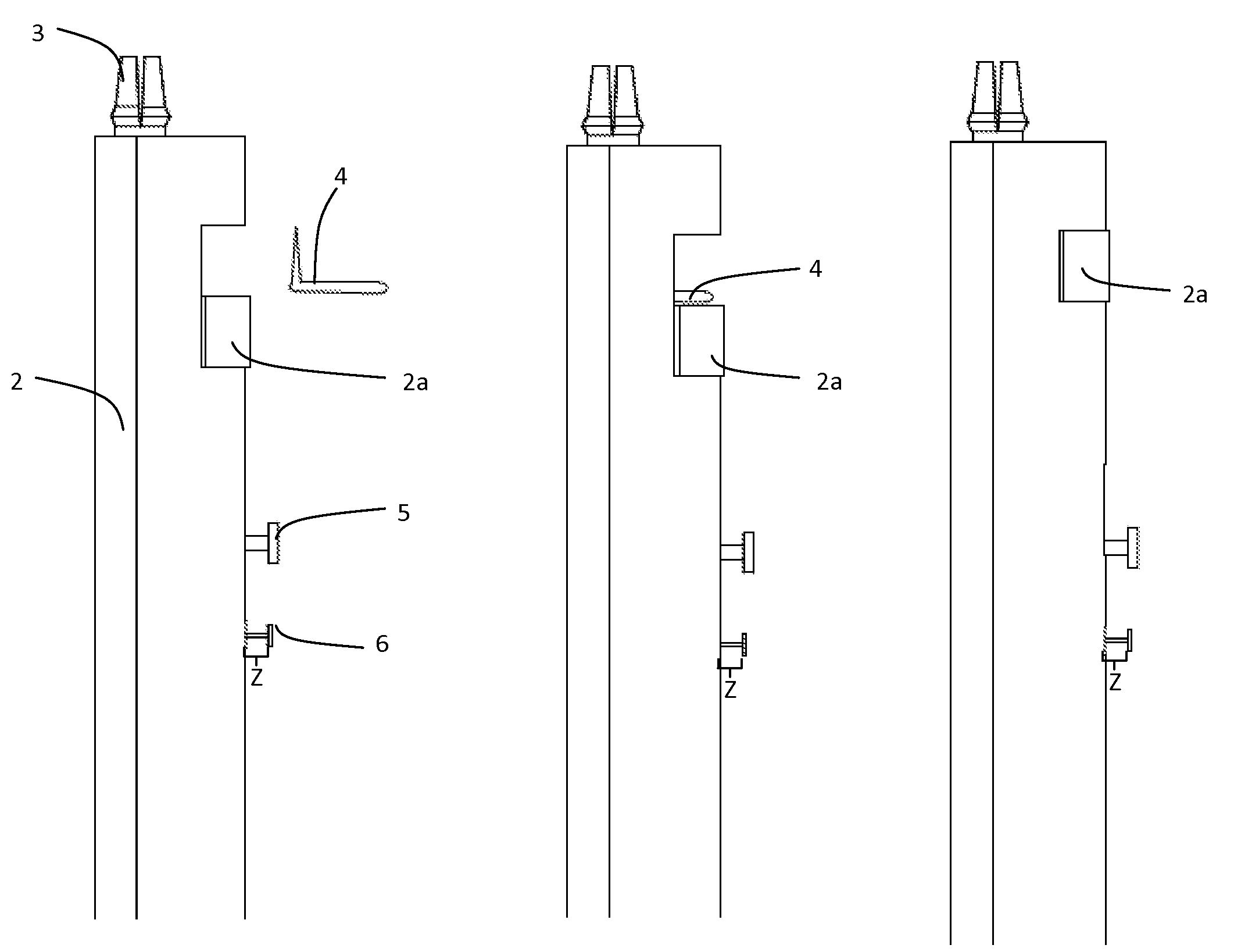
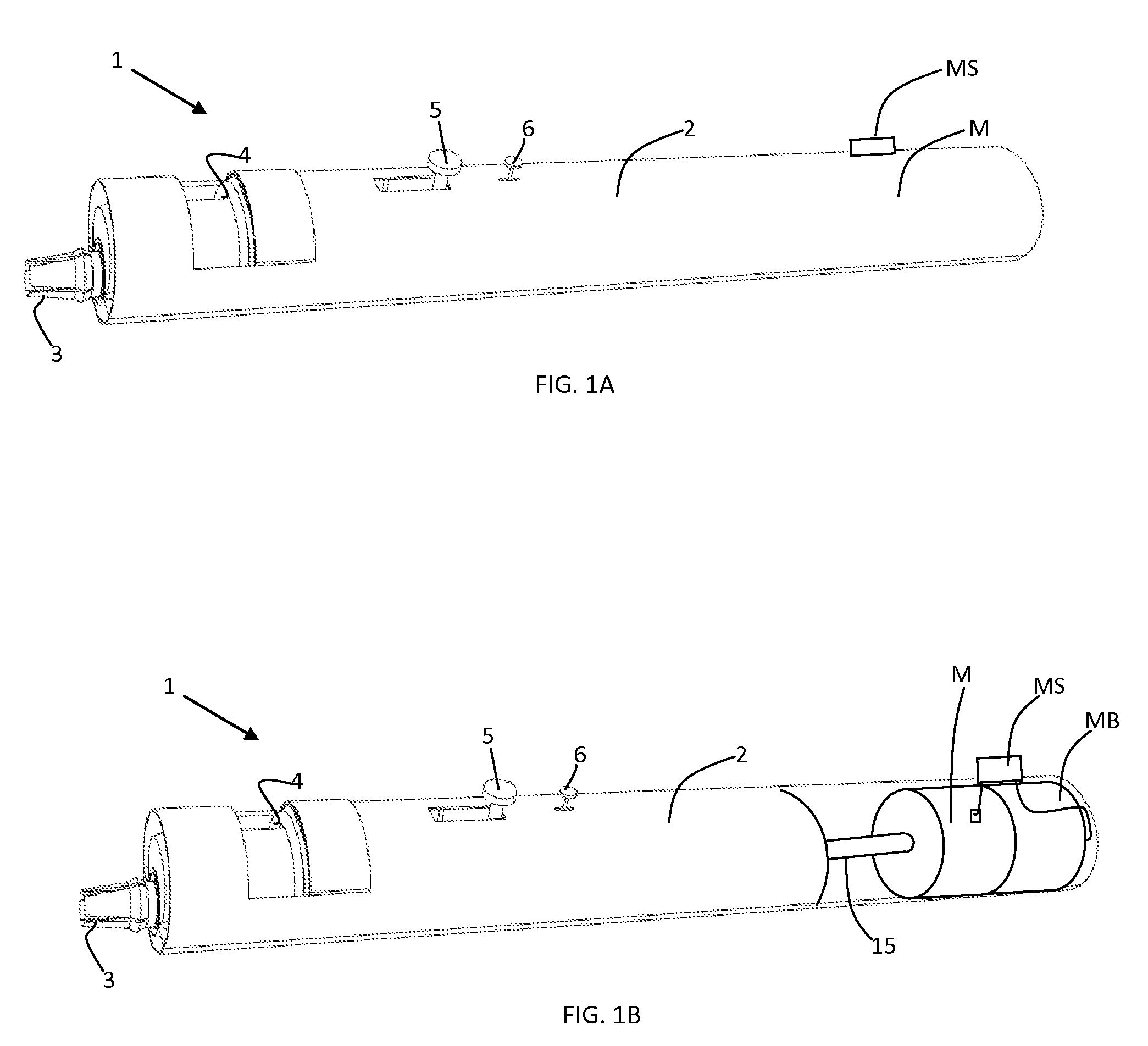
[0047]FIG. 1A shows an exemplary biopsy punch device in accordance with the principles of the present application. The first embodiment for a biopsy punch device 1 constructed in accordance with this application comprises an elongated hollow body housing 2 with a distal end having an exposed cylindrical cutter 3, a sutureless fastener member 4, loading shaft 5, a trigger 6 and a automatic system comprising a motor M and a control system MS.

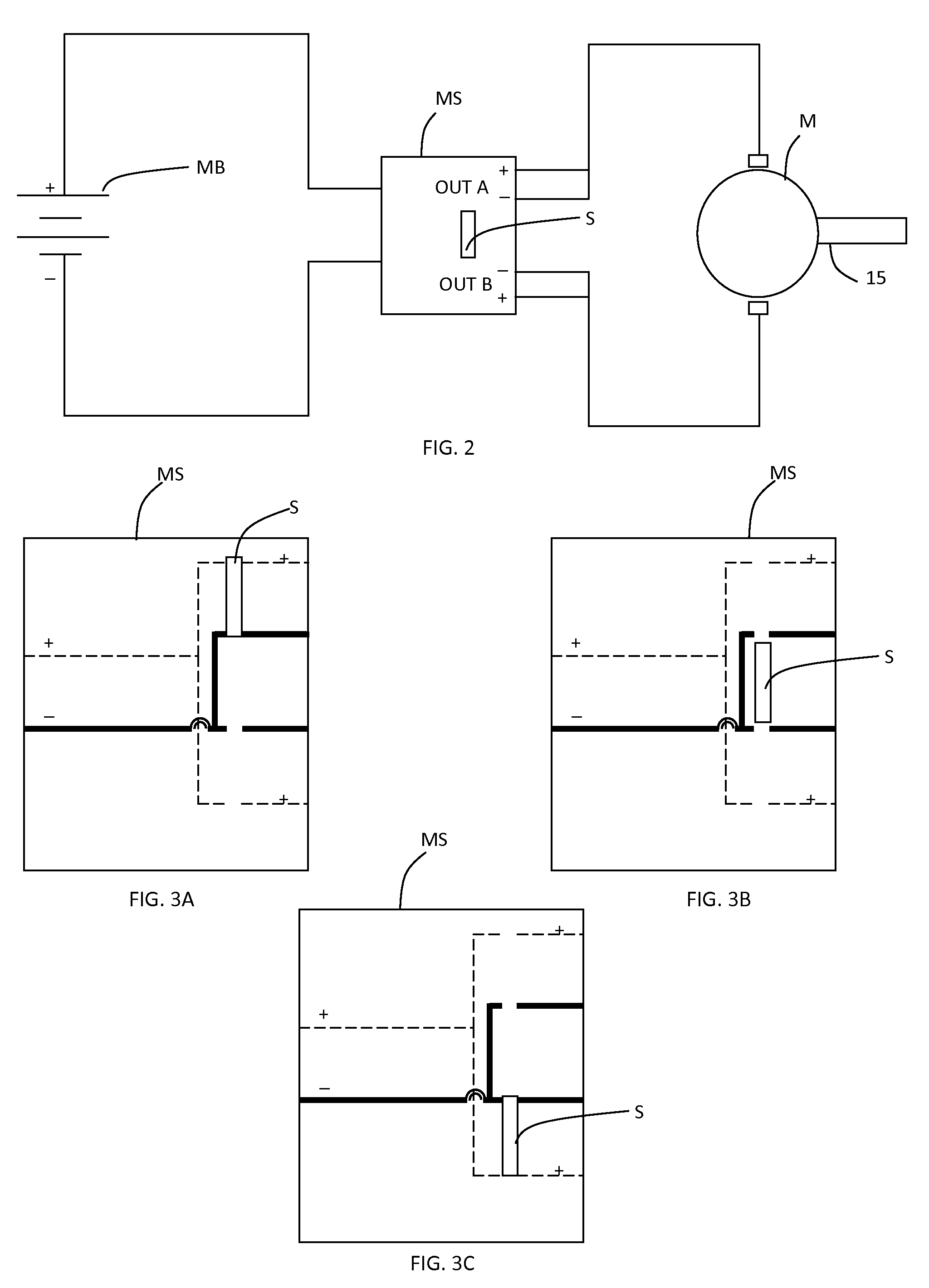
[0048]The automation system is mechanically coupled to the biopsy punch cutter 3 assembly, wherein the automation system is located at the proximal end of the elongated hollow body 2. The automation system comprises a power supply or battery MB electrically coupled to the motor M by means of a rotation control system MS, wherein the rotation control system MS regulates the behavior of the motor M, more particularly the rotation of the motor shaft 15, as shown in FIG. 1B, which is mechanically coupled to the biopsy punch cutter 3 assembly.

[0049]FIG...


PUM


Abstract

A dermal punch device for automatically extracting a sample of tissue of a predetermined size and shape from a body comprising a retractable cutter and a sutureless biopsy closure mechanism that includes a wound closure fastener member adapted to be disposed over a biopsy region after the performance of the biopsy, wherein wound closure fastener member is applied without the need of several instruments to seal the wound. The wound closure fastener member is dispensed by a sutureless biopsy closure dispenser located at the same distal end of the biopsy punch device surrounding the biopsy punch cutter assembly avoiding the need of separates instruments, reducing the wound closing steps and surgical procedure time.

Description

STATEMENT REGARDING FEDERALLY SPONSORED RESEARCH AND DEVELOPMENT[0001]N / ARELATED APPLICATIONS[0002]N / ABACKGROUND OF THE INVENTION[0003]1. Field of the Invention[0004]This application relates generally to the field of extracting tissue samples from solid bodies, and more specifically to surgical instruments for extracting a biopsy or sample of tissue while providing a sutureless biopsy wound site closure.[0005]2. Discussion of the Background[0006]Annually thousands of persons and animals are tested for numerous skin problems such as abnormal skin growths and cancers, as well as skin eruptions. Surgical instruments, such as a dermal punch and others are used to obtain samples of skin lesions for diagnostic purposes. The procedure involves the insertion of a cutting surgical instrument into the patient's skin wherein the cutting surgical instrument comprises a cylindrical blade at the distal end of an inert plastic or metal rod. After abutting the cylindrical blade to the skin the cutt...

Claims


Application Information

Patent Timeline
Patent Type & Authority Patents(United States)
IPC IPC(8): A61B10/00
CPCA61B10/0233A61B17/0057A61B17/0644A61B17/0682A61B2010/0208A61B2017/00592A61B2017/00623A61B2017/00668A61B17/32053A61B2017/0645
Inventor MENDEZ-COLL, JOSE ARTURO
Owner MENDEZ COLL JOSE ARTURO
Why Eureka
Try Eureka