
Magnetic head having a contact sensor

a contact sensor and magnetic head technology, applied in the field of magnetic head, can solve the problems of increasing the current density increasing the heat generated by the contact sensor itself, and reducing the service life so as to improve the reliability of the contact sensor, without adversely affecting the recording medium and the write characteristics

Inactive Publication Date: 2013-09-24
TDK CORPARATION
View PDF20 Cites 4 Cited by
  • Summary
  • Abstract
  • Description
  • Claims
  • Application Information

AI Technical Summary

Benefits of technology

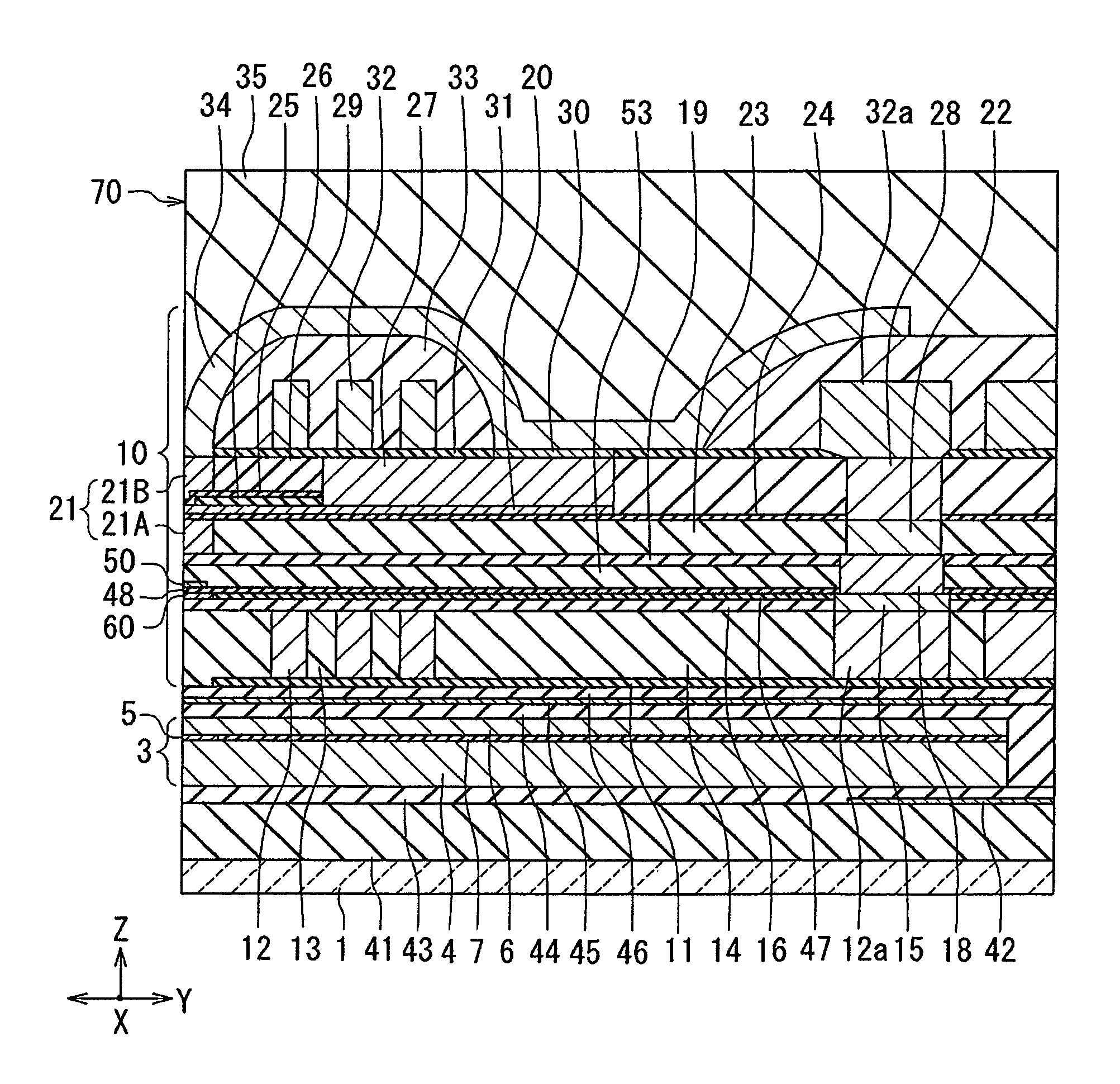
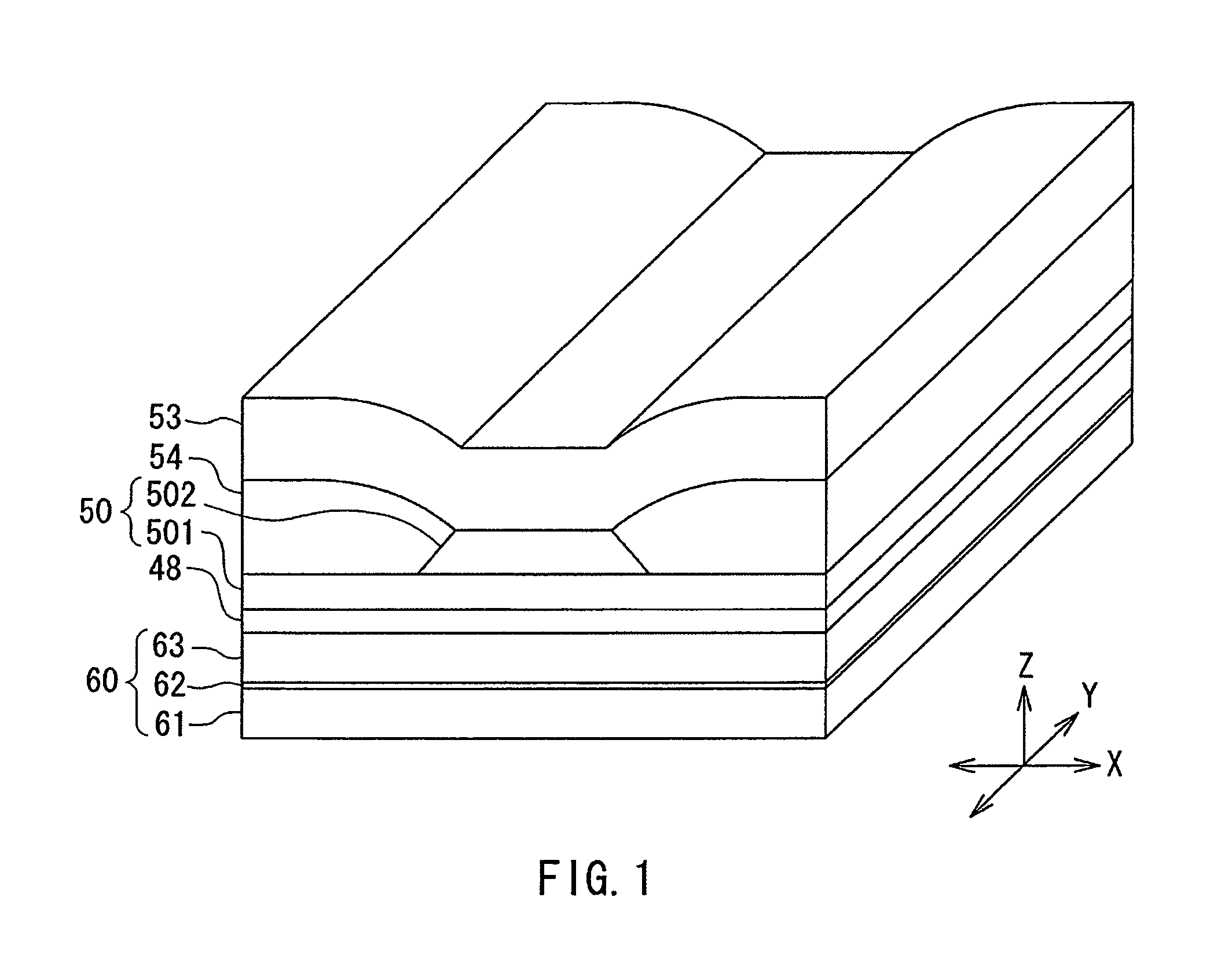
The present invention provides a magnetic head with a write head section and a contact sensor that can detect temperature variations. The magnetic head has a heat sink that reduces the magnetic field directed toward the recording medium from the end face of the heat sink, preventing adverse effects on the recording medium and the write characteristics of the write head section. This improves the reliability of the contact sensor without degrading its sensitivity. The heat sink includes two ferromagnetic layers that are antiferromagnetically exchange-coupled to each other via an intermediate layer, resulting in a reduced magnetic field directed toward the recording medium. The magnetic head, head assembly, and magnetic recording device of the present invention make it possible to improve the reliability of the contact sensor without affecting its sensitivity or the recording medium and write characteristics.

Problems solved by technology

On the other hand, however, increasing the voltage applied to the contact sensor increases the current density of the contact sensor and also increases the amount of heat generated by the contact sensor itself.
This causes electromigration to become noticeable and results in a reduction in service life of the contact sensor, thus leading to degradation in reliability of the contact sensor.
For a heat sink that is to be provided adjacent to the contact sensor in a magnetic head, however, some materials may give rise to the following problem due to the method of manufacturing the magnetic head.
In such a case, the sensitivity of the contact sensor may be reduced, or the write characteristics of the write head section and the read characteristics of the read head section may deteriorate.
On the other hand, if the end face of each of the heat sink and the contact sensor is protruded relative to the end face of each of the write head section and the read head section, the distance between the surface of the recording medium and the end face of each of the write head section and the read head section in the medium facing surface is not sufficiently small at the point in time at which the contact sensor has detected a contact.
Consequently, in this case, the write characteristics of the write head section and the read characteristics of the read head section may deteriorate.
The magnetic field may adversely affect the recording medium or the write characteristics of the write head section.

Method used


Image

  • Magnetic head having a contact sensor
  • Magnetic head having a contact sensor
  • Magnetic head having a contact sensor

Examples


modification example

[Modification Example]

[0116]A modification example of the embodiment will now be described. FIG. 16 is a perspective view showing a heat sink of the modification example of the embodiment. The heat sink 80 of the modification example has a plurality of ferromagnetic layers 81 and a plurality of intermediate layers 82 that are alternately stacked. Two of the plurality of ferromagnetic layers 81 are disposed at opposite ends of the heat sink 80 in the stacking direction. In the example shown in FIG. 16, the number of the ferromagnetic layers 81 is six, and the number of the intermediate layers 82 is five. The material of the ferromagnetic layers 81 is the same as that of the ferromagnetic layer 61 or 63. The material of the intermediate layers 82 is the same as that of the intermediate layer 62.

[0117]In the modification example, any two ferromagnetic layers 81 that are vertically adjacent to each other with one of the intermediate layers 82 therebetween are antiferromagnetically excha...


PUM

PropertyMeasurementUnit
thicknessaaaaaaaaaa
thicknessaaaaaaaaaa
thicknessaaaaaaaaaa

Abstract

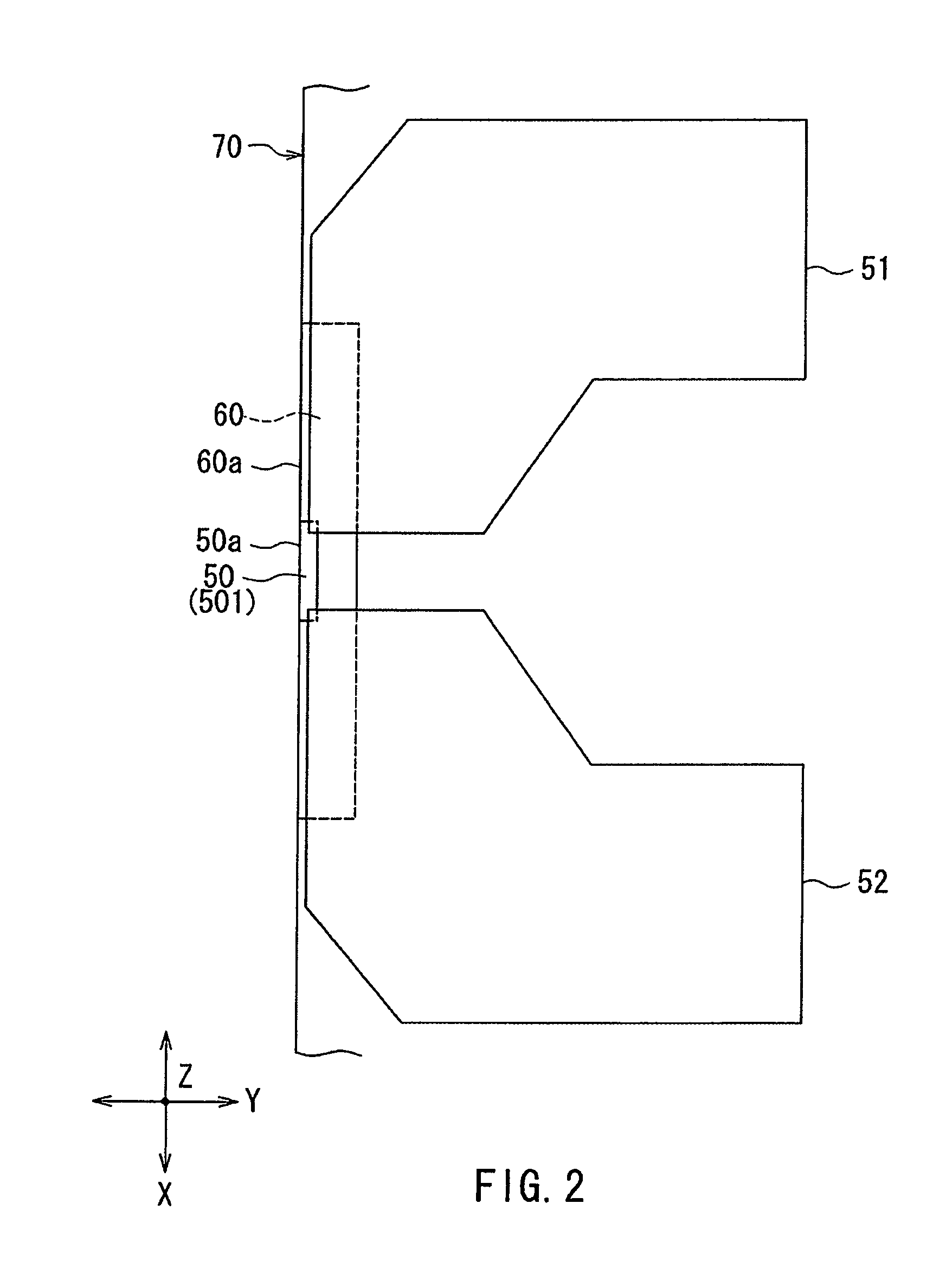
A magnetic head includes a medium facing surface that faces a surface of a recording medium, a write head section, a contact sensor that detects contact of the medium facing surface with the surface of the recording medium, and a heat sink adjacent to the contact sensor. The write head section has a magnetic pole that produces a write magnetic field for writing data on the recording medium. The contact sensor and the heat sink have respective end faces located in the medium facing surface. The contact sensor varies in resistance in response to temperature variations, and is to be energized. The heat sink includes an intermediate layer made of a nonmagnetic metal material, and two ferromagnetic layers made of a metal-based magnetic material, the two ferromagnetic layers being disposed with the intermediate layer therebetween, and being antiferromagnetically exchange-coupled to each other via the intermediate layer.

Description

BACKGROUND OF THE INVENTION[0001]1. Field of the Invention[0002]The present invention relates to a magnetic head that is used for writing data on a recording medium, and more specifically, to a magnetic head having a contact sensor.[0003]2. Description of the Related Art[0004]Recently, magnetic recording devices such as magnetic disk drives have been improved in recording density, and magnetic heads of improved performance have been demanded accordingly. Among the magnetic heads, a composite thin-film magnetic head has been used widely. The composite thin-film magnetic head has such a structure that a read head section including a magnetoresistive element (hereinafter, also referred to as MR element) for reading and a write head section including an induction-type electromagnetic transducer for writing are stacked on a substrate. In a magnetic disk drive, the magnetic head is mounted on a slider that flies slightly above the surface of a recording medium. The magnetic head has a med...

Claims


Application Information

Patent Timeline
Patent Type & Authority Patents(United States)
IPC IPC(8): G11B5/127G11B5/02G11B5/48G11B21/02
CPCG11B5/607G11B5/6076G11B5/3133G11B5/3136G11B5/3146
Inventor YAMANE, TAKEKAZUANTOKU, YOSUKEKURIHARA, KATSUKITAKAHASHI, NORIOMAKINO, KENZO
Owner TDK CORPARATION
Learn More