Method for determining flow conditions

a flow condition and measurement volume technology, applied in the field of measuring volume flow conditions, can solve the problems of large errors in the determination of 3-dimensional particle positions, inaccurate and faulty determination of 2-dimensional particle positions, and comparatively small particle numbers in the measuring volume, so as to achieve greater displacement vector density and particle density. the effect of density

Active Publication Date: 2013-09-24
LAVISION
View PDF7 Cites 3 Cited by
  • Summary
  • Abstract
  • Description
  • Claims
  • Application Information

AI Technical Summary

Benefits of technology

[0008]The object of the present invention is to further develop a generic method such that, based on known 3D-PTV techniques, a greater particle density in the measuring volume can be processed and thus a greater density of displacement vectors in the resulting three-dimensional displacement vector field can be achieved.
[0019]The optical transfer function must be known in order to calculate the virtual images essential for the present invention from an assumed particle distribution in the measuring volume. The accuracy with which the optical transfer functions are known determines the accuracy of the method according to the invention. The optical transfer functions can be determined in a simple manner by calibration, in particular by recording real images of one or more known objects in the measuring volume and comparing the known object or objects to the recorded images. To this end, for example, a calibration plate with markings of known size and arrangement can be positioned at different positions in the measuring volume and respectively recorded. It can be accurately determined from the resulting images how different regions of the measuring volume are imaged. Alternatively to the calibration plate, a calibration grid can also be used, i.e., a three-dimensional distribution of markings of known size and arrangement. If the markings are sufficiently small on the calibration plate or calibration grid, “mapping” and MTF determination can be carried out at the same time. With larger markings, “mapping” and MTF determination are typically carried out in separate calibration steps.

Problems solved by technology

A disadvantage of this method lies in its limitation to comparatively small particle numbers and particle densities in the measuring volume.
A particle density that is too large leads in the imaging of the three-dimensional measuring volume to multiple overlapping of the images of the particles in the camera images recorded, so that the determination of the 2-dimensional particle positions is inaccurate and faulty.
In the triangulation, major errors thus occur in the determination of the 3-dimensional particle positions.
However, this approach can be pursued only to a limited extent due to reasons of space and cost.
However, the method is very computationally intensive and therefore time-consuming.

Method used


Image

  • Method for determining flow conditions
  • Method for determining flow conditions
  • Method for determining flow conditions

Examples


Embodiment Construction

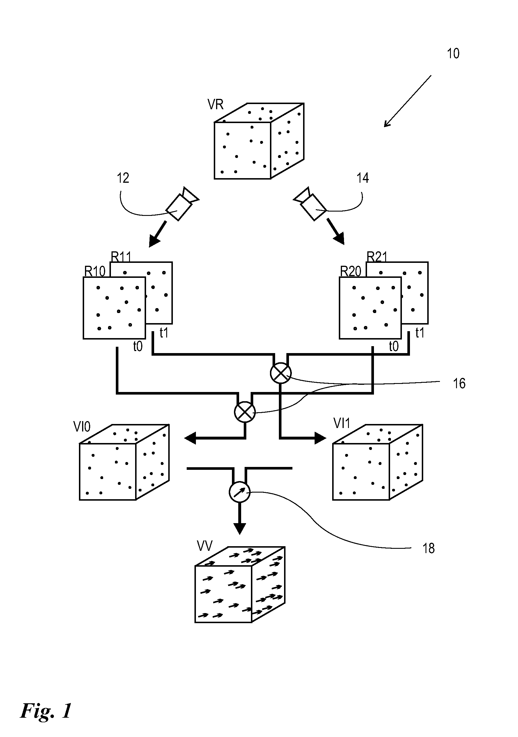
[0025]FIG. 1 shows a diagrammatic representation of the 3D-PTV method, the generality of which, as depicted, is known by one skilled in the art. The starting point is a real volume VR, which represents a measuring volume, which is flowed through by a fluid which is seeded with optically detectable particles. Preferably fluorescent or reflecting particles are used, which are preferably embodied identically or at least in a similar manner, and the density thereof is adapted in particular to the fluid density. For example, hollow or filled glass or plastic beads or—in particular in gas flows—droplets of liquid, can be used. However, in principle it is also possible to use irregular particles, such as, for example, carbon black particles.

[0026]The measuring volume VR is recorded by a plurality of image detectors 12, 14 to produce real images. In the embodiment shown, two detectors 12, 14 are illustrated. However, it is likewise possible to use more than two detectors. It is necessary fo...


PUM


Abstract

The invention relates to a method for determining flow conditions in a measured volume permeated by a fluid spiked with optically detectable particles. A plurality of two-dimensional images of the particle distribution is thereby created at each of a plurality of times, an estimated particle distribution is determined therefrom, and a three-dimensional displacement vector field is calculated. According to the invention, a transfer function for the image detectors used is first determined, by means of which the real distribution is mapped by the image detector. Starting from a roughly estimated initial distribution, and by means of the transfer function, virtual images of the estimated distribution are then calculated and compared to the associated real images. The estimated distribution is modified in an iterative method until sufficient matching of the virtual and real images has been achieved.

Description

BACKGROUND OF THE INVENTION[0001](1) Field of the Invention[0002]The invention relates to a method for determining flow conditions in a measuring volume, which is flowed through by a fluid seeded with optically detectable particles, comprising the following steps:[0003]a) Simultaneous recording at a first recording point in time of a first plurality of two-dimensional, real images of a three-dimensional, real distribution of the particles by means of the same plurality of image detectors arranged spatially offset with respect to one another,b) Repetition of Step a, at least at one second recording point in time,c) For each recording point in time: determination of a three-dimensional, estimated distribution of the particles based on the real images andd) Calculation of a three-dimensional displacement vector field by comparing the estimated distributions.[0004](2) Description of Related Art[0005]Methods of this type are known as 3D-PTV, Three-Dimensional Particle Tracking Velocimetr...

Claims


Application Information

Patent Timeline
Patent Type & Authority Patents(United States)
IPC IPC(8): G06K9/62
CPCG01P5/001
Inventor WIENEKE, BERHNARD
Owner LAVISION
Why Eureka
Try Eureka