Subcutaneous device for electrical percutaneous connection

a technology of electrical percutaneous connection and subcutaneous device, which is applied in the direction of coupling device connection, electrotherapy, medical/surgical connector, etc., can solve the problems of limited use possibilities of connection type, insufficient battery installation, and insufficient long-lasting power

Inactive Publication Date: 2013-10-01
CENT HOSPITALER UNIV DE ROUEN
View PDF87 Cites 12 Cited by
  • Summary
  • Abstract
  • Description
  • Claims
  • Application Information

AI Technical Summary

Benefits of technology

[0033]According to another aspect of the invention, an external device for electrical connection is proposed especially suited to the system proposed permitting a percutaneous electrical connection. More precisely, an external device for electrical connection is proposed for the proposed electrical connection system, having electrical connection plugs in the form of penetrating pins designed to be inserted from the outside of the animal body percutaneously inside the compartments of the housing of the subcutaneous device, characterized in that it further comprises alignment means for facilitating positioning and guiding the insertion of the electrical connection plugs into the corresponding conductive materials of the subcutaneous device housing.

Problems solved by technology

However, implanted batteries are insufficient to provide long lasting power, especially for implanted medical devices requiring substantial electrical power, such as implanted ventricular assist devices or total artificial hearts, to name only two applications concerning cardio-thoracic surgery.
Once again, this type of connection has limited possibilities for use and is therefore somewhat restricted, since the transfer of high power energy requires antennas of a size that are poorly compatible with a normal life.

Method used


Image

  • Subcutaneous device for electrical percutaneous connection
  • Subcutaneous device for electrical percutaneous connection
  • Subcutaneous device for electrical percutaneous connection

Examples


Embodiment Construction

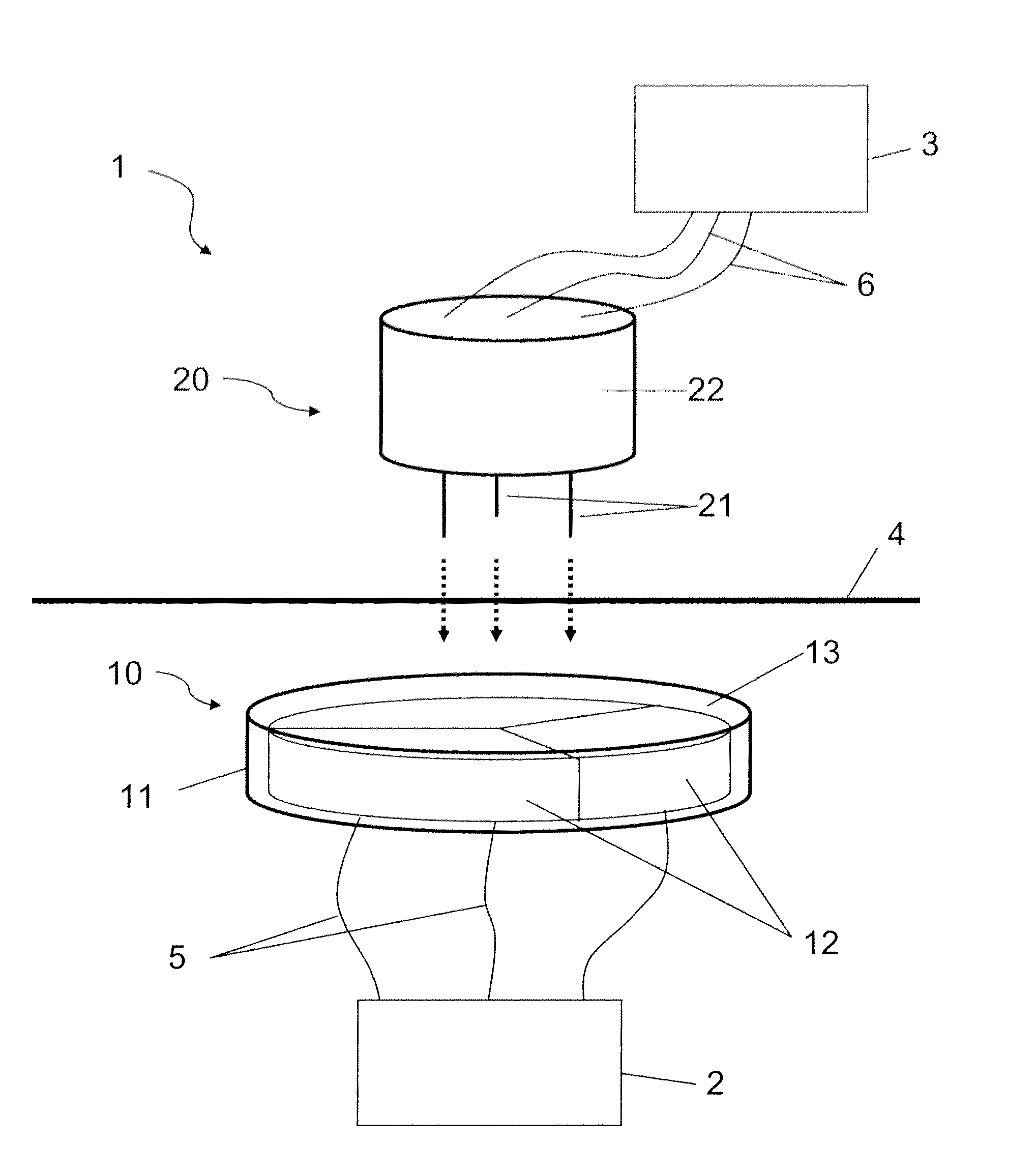
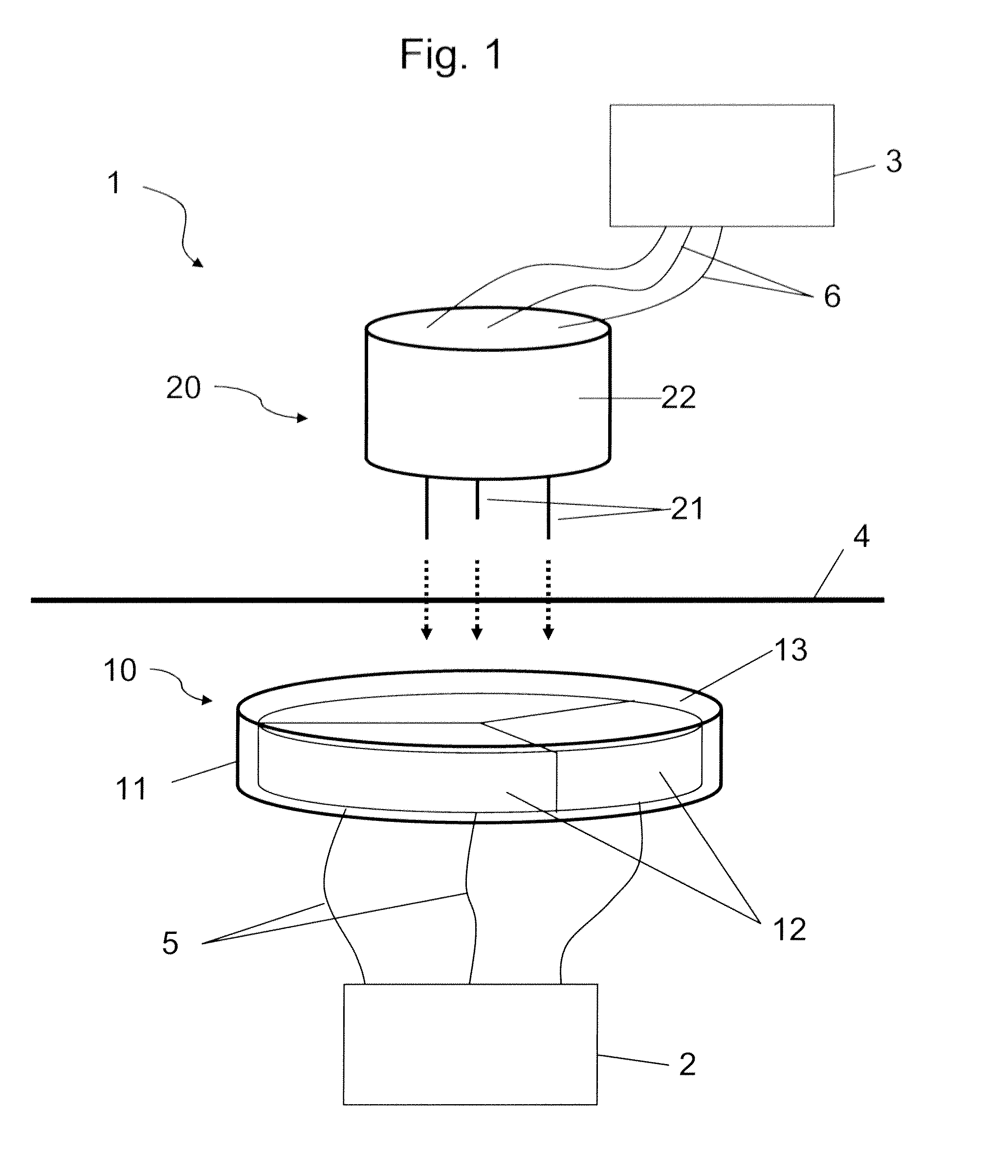
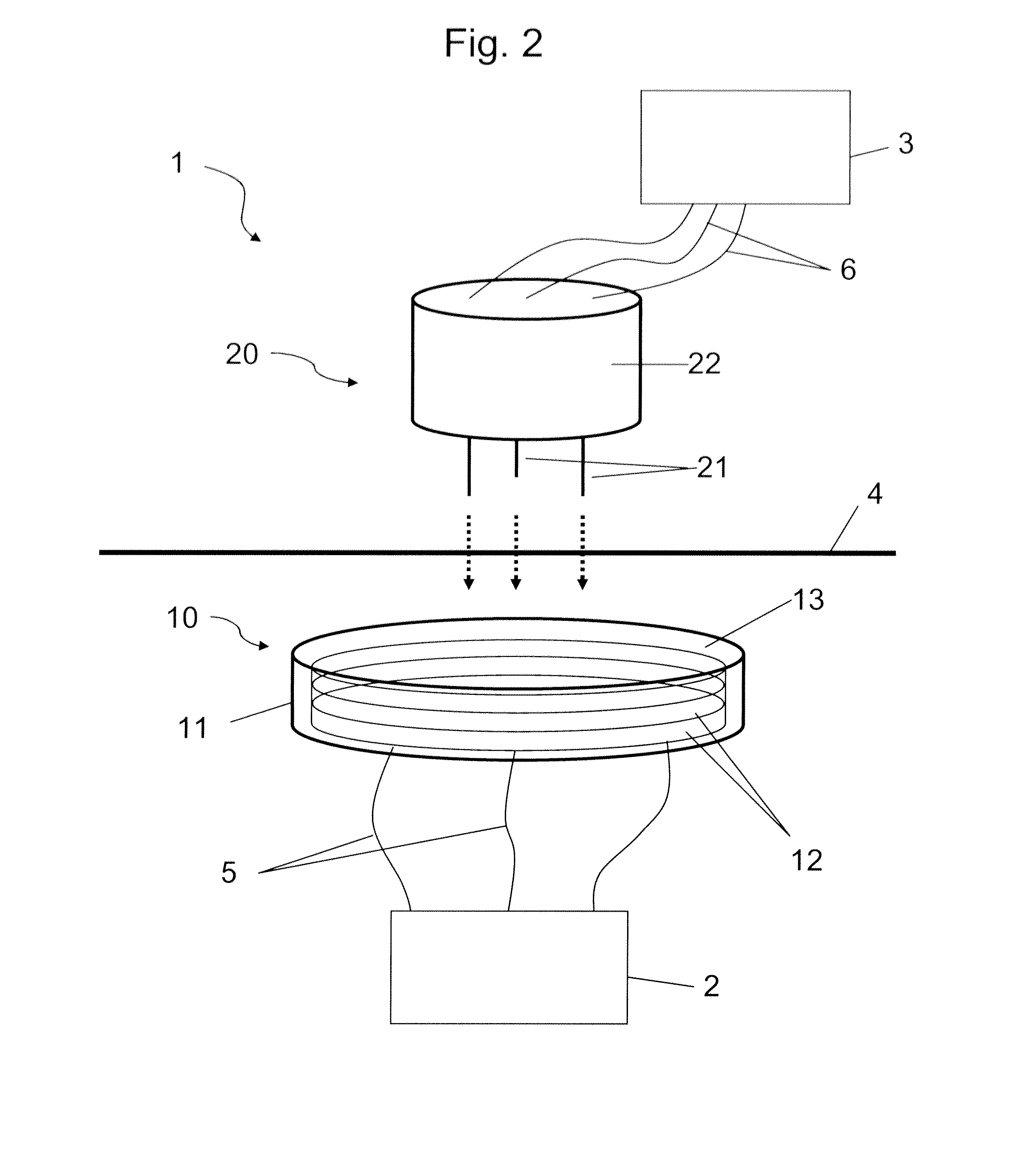
[0039]The general principle of the percutaneous electrical connection system presented here resides in the use of a subcutaneous device for electrical connection. By subcutaneous device is meant a device that is designed to be implanted in the patient and positioned subcutaneously and which therefore includes all the means necessary for such a subcutaneous implantation, especially in terms of biocompatibility of the materials, a suitable shape for subcutaneous positioning and corresponding position maintenance, etc.

[0040]The subcutaneous electrical connection device is therefore designed to be positioned subcutaneously in the patient and is connected electrically to an internal electrical device implanted in the patient's body. As we will see in more detail below, the subcutaneous device is further designed to be connected to an external electrical device by means of electrical connection plugs in the form of penetrating pins that can be inserted through the patient's skin from outs...


PUM


Abstract

The invention concerns an electrical connection system for a percutaneous electrical connection between an electrical device (2) inside an animal body and an electrical device (3) outside said body, comprising a subcutaneous device (10) designed to be connected to internal electrical device (2), said subcutaneous device (10) comprising:an open housing (11) having at least one inner compartment (12), said compartment (12) being filled with a conductive material into which an electrical connection plug can be inserted, the conductive material of compartment (12) being further connected to connection means (5) designed to be connected to internal electrical device (2);a sealing membrane (13) for sealing housing (11), said sealing membrane (13) being formed of an insulating and flexible material designed for insertion of electrical connection plugs from outside housing (11) through said sealing membrane (13) to the conductive material of compartment (12);characterized in that housing (11) comprises alignment means (14) to facilitate positioning and to guide the insertion of electrical connection plugs into the corresponding conductive materials.

Description

[0001]This is non-provisional application claiming the benefit of International application number PCT / EP2010 / 055430 filed Apr. 23, 2010.FIELD OF THE INVENTION[0002]The present invention concerns electrical connections in the medical field, and more particularly a system permitting a percutaneous electrical connection between a medical device implanted in the body of an animal, in particular in the human body, and an electrical device outside the body.TECHNICAL BACKGROUND[0003]The significant development of electrical equipment designed to be installed inside the patient's body to compensate for a defect in a natural organ, requires being able to transmit either the power required by this equipment from a power source outside the body to the inside of the body, or to collect electrical information originating from the defective natural organ and / or electrical equipment designed to compensate for these defects.[0004]For this electrical implanted equipment, power is currently provided...

Claims


Application Information

Patent Timeline
Patent Type & Authority Patents(United States)
IPC IPC(8): H01R4/24A61N1/00
CPCA61M1/127H01R3/08H01R4/24H01R13/5224A61N1/3752H01R13/6205H01R2201/12H01R4/2404A61M60/88A61M60/178A61M60/875
Inventor LITZLER, PIERRE-YVESSABIN, PIERRE
Owner CENT HOSPITALER UNIV DE ROUEN
Why Eureka
Try Eureka