Cardiac support systems and methods for chronic use

a technology of cardiac support system and continuous flow, which is applied in the direction of inductance, prosthesis, other medical devices, etc., can solve the problems of high power consumption, inability to implant a power source of sufficient capacity for a full day of awake hours of operation in the body, and inability to meet the needs of patients

Active Publication Date: 2013-10-08
CORVION INC
View PDF34 Cites 72 Cited by
  • Summary
  • Abstract
  • Description
  • Claims
  • Application Information

AI Technical Summary

Problems solved by technology

Currently available implantable continuous flow blood pumps consume significantly more electric power to produce the desired amount of flow and pressure.
High pump power consumption of current systems may make it impractical to implant a power source of sufficient capacity for a full day of awake hours of operation in the body.
For example, size restrictions of implantable power sources may only allow the implantable power source to provide up to an hour of operation time.
Instead, high power consumption blood pumps may provide a wire connected to the pump that exits the body (i.e. percutaneous) for connection to a power source that is significantly larger than an implantable power source.
However, percutaneous wires and externally worn components can still restrict the mobility of a person with such a blood pump implant.
For example, such high power consumption blood pumps have external batteries that frequently require recharging thereby limiting the amount of time the person can be away from a charger or power source, external batteries and controllers that can be heavy or burdensome thereby restricting mobility, percutaneous wire skin penetrations that are not suitable for prolonged exposure to water submersion (i.e. swimming, bathing, etc.), and / or other additional drawbacks.
For example, negative impacts of these types of systems may include susceptibility to infection, constraints on sleep position, restrictions on water activities such as swimming and bathing, concern for wire entanglement or severing, necessity to avoid static discharges, and a multitude of others.
Furthermore, the external batteries and control systems are burdensome.
While there is limited use of wireless power systems in some neural stimulators, widespread use of wireless power systems for implantable heart pumps has not been adopted.
Currently, few applications of wireless power transfer have been applied to VADs or TAHs due to the higher power transfer levels required, relatively high power consumption of such devices, limited space available for implantable rechargeable batteries, limited capacity of implantable rechargeable batteries, and the like.
These inductive systems can generate significant amounts of heat near the skin, and require the patient to be immobile during charging if the external power source is not easily mobile.
Energy lost by such systems is generally released as heat that is dissipated into the human body, which may produce heat-related health complications or require additional components to compensate for the heat generated.
These systems eliminated the wire, but did not eliminate the burdensome external batteries and control system which still had to be worn by the patient.
However, due to the energy demands of the implanted system, that implantable battery could supply only about 20 minutes of energy.
Implantable cardiac support systems have numerous sources of potential energy inefficiency.
As a result of the significant drawbacks of existing systems, there is an unmet need for an energy-efficient cardiac support system capable of eliminating percutaneous wires for power or control, and doing so without burdening the patient with external batteries or controllers.

Method used


Image

  • Cardiac support systems and methods for chronic use
  • Cardiac support systems and methods for chronic use
  • Cardiac support systems and methods for chronic use

Examples


Embodiment Construction

[0047]Refer now to the drawings wherein depicted elements are not necessarily shown to scale and wherein like or similar elements may be designated by the same reference numeral through the several views.

[0048]Referring to the drawings in general, it will be understood that the illustrations are for the purpose of describing particular implementations of the disclosure and are not intended to be limiting thereto. While most of the terms used herein will be recognizable to those of ordinary skill in the art, it should be understood that when not explicitly defined, terms should be interpreted as adopting a meaning presently accepted by those of ordinary skill in the art.

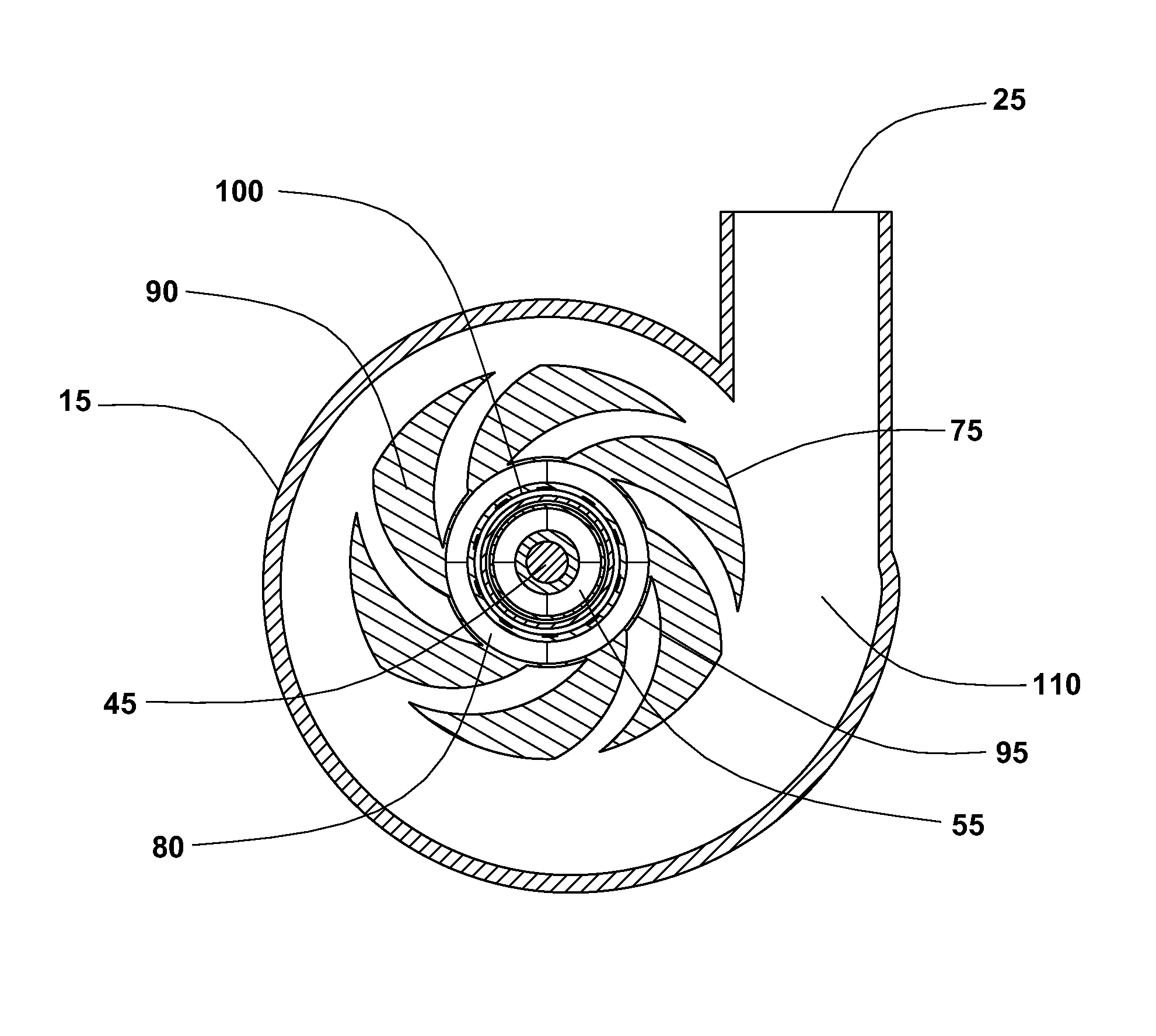
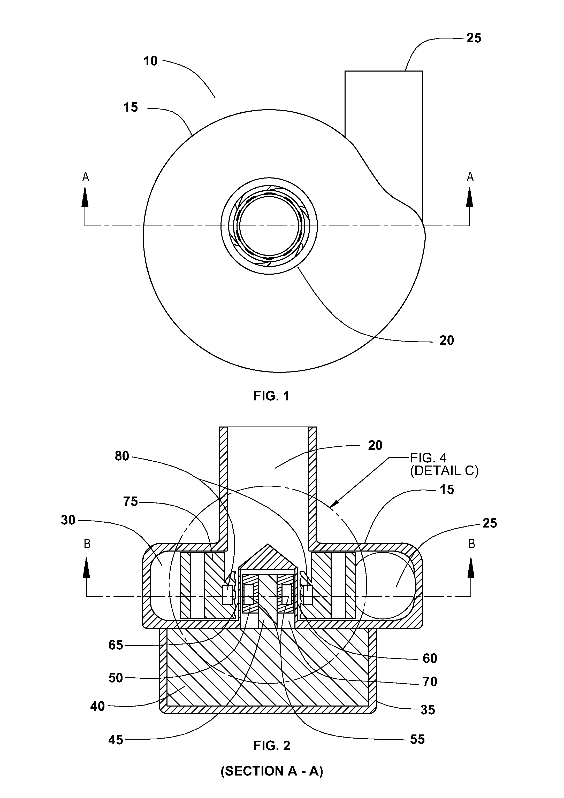
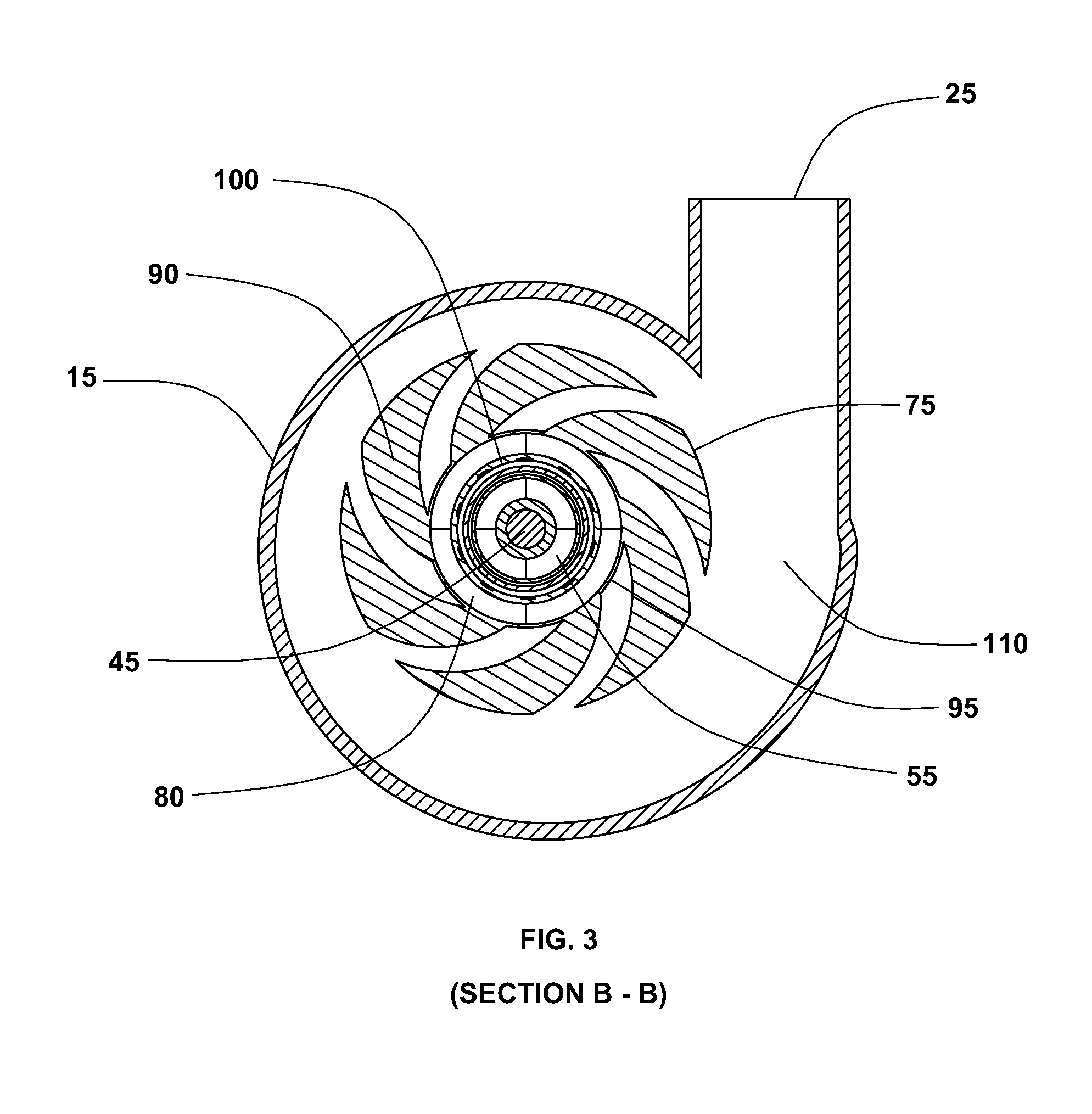
[0049]The following detailed description provides for an implantable, energy efficient, small, and wireless cardiac support system. The cardiac support system may include an implantable rotary blood pump, an implantable power module, and a wireless power transfer subsystem. The implantable rotary blood pump may be pow...


PUM


Abstract

A high efficiency cardiac support system is suitable for chronic use in treating heart failure, wherein the system includes an implantable rotary blood pump, an implantable power module, a wireless power transfer subsystem, a patient monitor, and a programmer. In a cardiac support system, the cumulative efficiencies of the components of the system are capable of providing therapeutically effective blood flow for a typical day of awake hours using the energy from a single wireless recharge of an implanted rechargeable energy source. Moreover, the implantable rechargeable energy source may be recharged during a normal sleep period of 8 hours or less. The system may provide full or partial cardiac support without the need for external wearable batteries, controllers, or cables.

Description

RELATED APPLICATIONS[0001]This application is a continuation-in-part of U.S. patent application Ser. No. 12 / 899,748 to Akkerman et al., filed on Oct. 7, 2010. This application claims the benefit of U.S. Provisional Patent Application No. 61 / 421,779 to Armstrong et al., filed on Dec. 10, 2010, which is incorporated herein by reference.FIELD OF THE INVENTION[0002]This invention relates to implantable cardiac support systems, particularly implantable blood pump systems for the treatment of heart failure.BACKGROUND OF INVENTION[0003]In patients with heart failure, there is a need for therapeutically enhancing blood flow using an implantable system. Cardiac support systems include, but are not limited to, left ventricular assist devices (LVADs), right ventricular assist devices (RVADs), using two devices to assist both ventricles as a bi-ventricular assist device (BiVADs), and total artificial hearts (TAHs). Ventricular assist devices (VADs) that are suitable for adults may call for appr...

Claims


Application Information

Patent Timeline
Patent Type & Authority Patents(United States)
IPC IPC(8): A61M1/10A61M60/178A61M60/226A61M60/422A61M60/515A61M60/873
CPCH02J7/025A61M1/1086H02J5/005H01F38/14A61M1/127A61M2205/8243H02J50/12H02J7/0068A61M60/232A61M60/824A61M60/422A61M60/178A61M60/226A61M60/515A61M60/873H02J2310/23A61M60/148
Inventor ABER, GREG S.AKKERMAN, NEIL H.ARMSTRONG, RANDOLPH K.
Owner CORVION INC
Why Eureka
Try Eureka