Drive unit of electric motor and motorized equipment using the drive unit

a technology of drive unit and electric motor, which is applied in the direction of motor/generator/converter stopper, electronic commutator, dynamo-electric converter control, etc., can solve the problems of increasing the body size of the drive unit, and increasing the number of parts, so as to reduce the manufacturing cost of the motorized equipment, reduce the body size of the drive unit, and reduce the manufacturing cost.

Active Publication Date: 2013-10-08
DENSO CORP
View PDF28 Cites 8 Cited by
  • Summary
  • Abstract
  • Description
  • Claims
  • Application Information

AI Technical Summary

Benefits of technology

[0011]It is an object of the present invention to provide a drive unit reducing its body size and to provide a motorized equipment using the drive unit. It is another object of the present invention to provide a drive unit reducing its manufacturing cost and to provide a motorized equipment using the drive unit.

Problems solved by technology

Therefore, there is a concern that a body size of the drive unit enlarges.
Therefore, the number of parts increases and a manufacturing cost increases.
Therefore, there is a concern that the body size of the drive unit enlarges.

Method used


Image

  • Drive unit of electric motor and motorized equipment using the drive unit
  • Drive unit of electric motor and motorized equipment using the drive unit
  • Drive unit of electric motor and motorized equipment using the drive unit

Examples


first embodiment

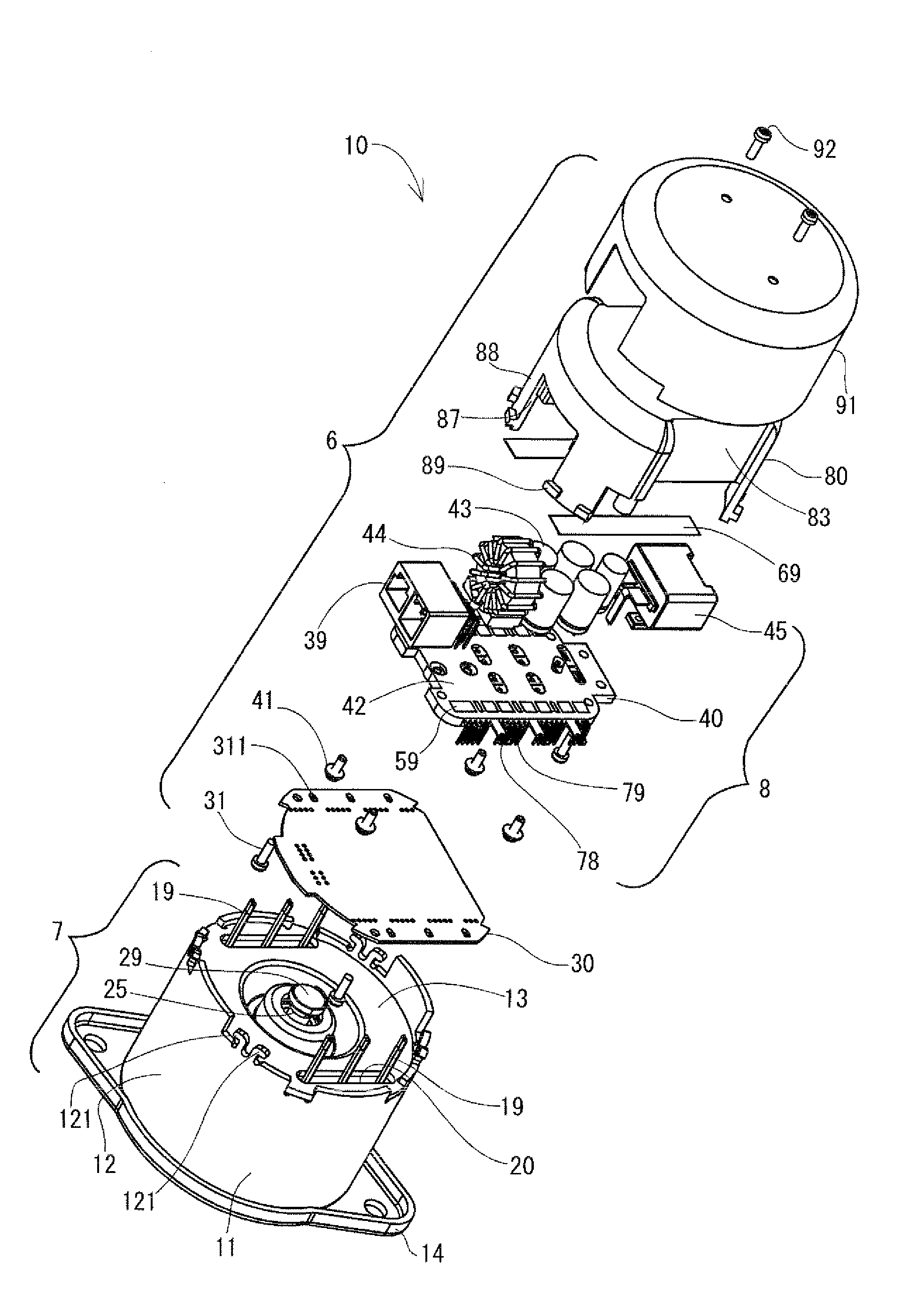
[0047]FIGS. 1 to 19 are diagrams each showing a motorized equipment according to a first embodiment of the present invention. The motorized equipment 10 according to the present embodiment is a brushless motor used for electric power steering. As shown in FIG. 6, the motorized equipment 10 meshes with a gear 2 of a column shaft 1. The motorized equipment 10 performs normal rotation and reverse rotation based on a vehicle speed signal, which is transmitted from CAN and the like, and a torque signal outputted from a torque sensor 4, which senses steering torque of a steering 3. Thus, the motorized equipment 10 generates a force for assisting steering.

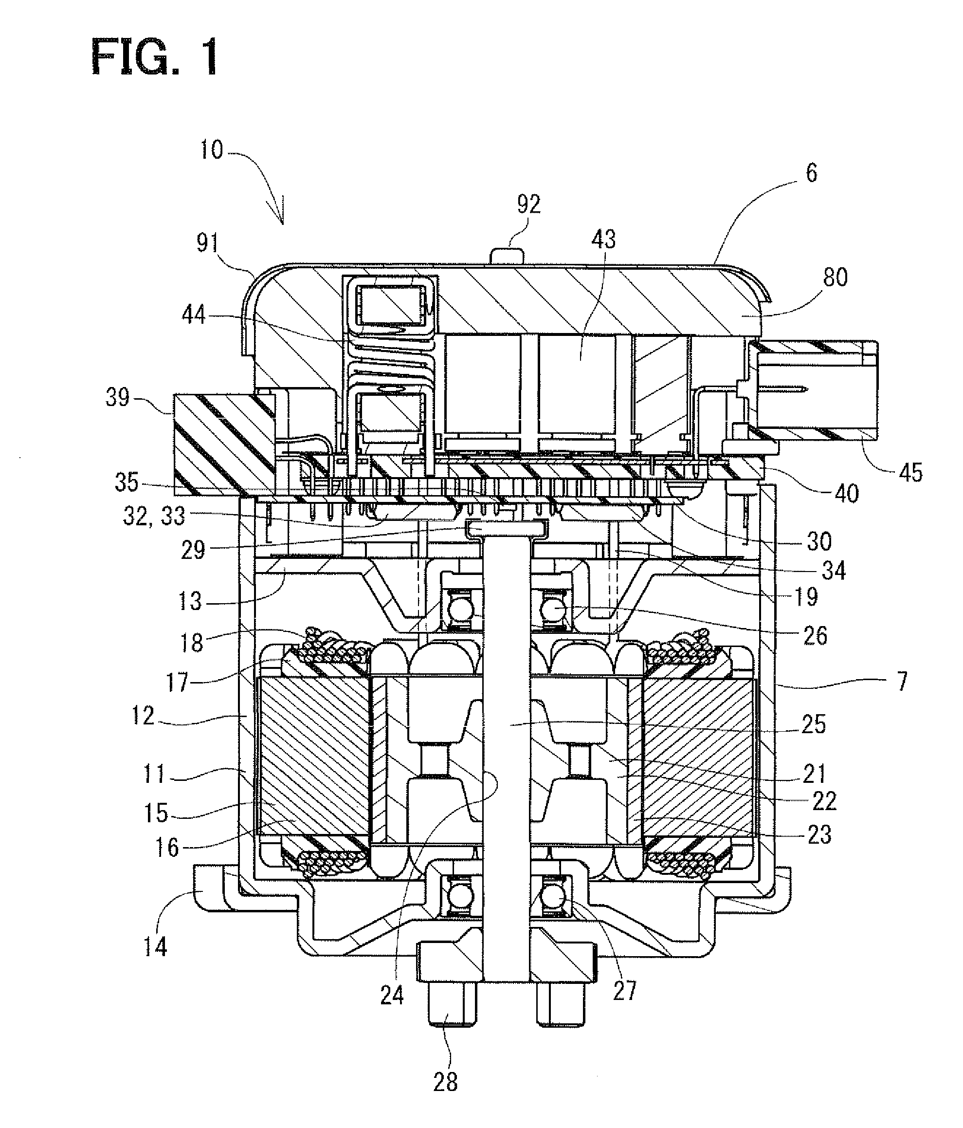
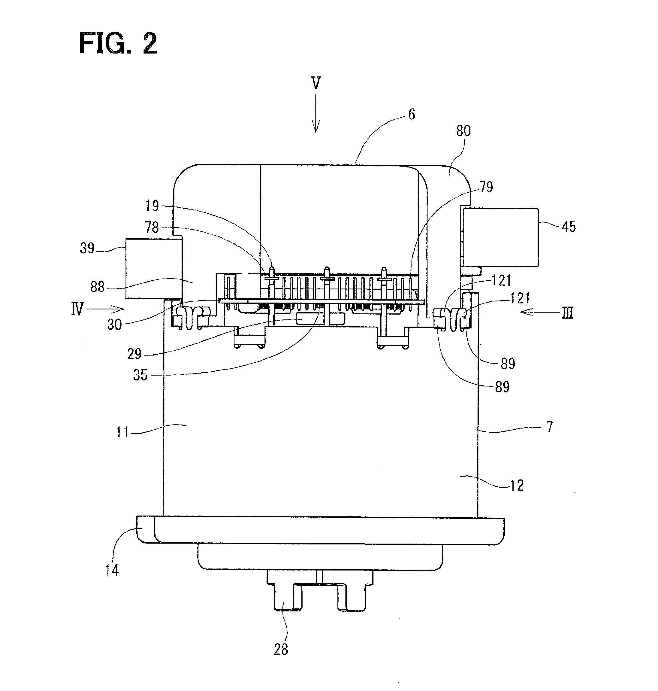
[0048]FIG. 1 is a cross-sectional view showing the motorized equipment 10 according to the present embodiment. FIGS. 2 to 5 are views each showing outer appearance of the motorized equipment 10 according to the present embodiment. FIG. 7 is an exploded perspective view showing the motorized equipment 10 according to the present embodiment...


PUM


Abstract

A power module of a drive unit of an electric motor is formed by inserting multiple power transistors, which supply a drive current to a coil wound around a stator or a rotor, and wirings connecting the power transistors in a resin, which is formed in the shape of a plate, by resin molding. Electronic components such as aluminum electrolytic capacitors, a choke coil and a first connector are provided in a board thickness direction of the power module and are electrically connected with the wirings of the power module. Thus, a construction for electrically connecting the wirings of the power module formed by the resin molding and the electronic components can be simplified.

Description

CROSS REFERENCE TO RELATED APPLICATION[0001]This application is based on and incorporates herein by reference Japanese Patent Application No. 2010-94789 filed on Apr. 16, 2010.BACKGROUND OF THE INVENTION[0002]1. Field of the Invention[0003]The present invention relates to a drive unit of an electric motor and a motorized equipment using the drive unit.[0004]2. Description of Related Art[0005]Conventionally, there has been publicly known a motorized equipment used for electric power steering for assisting steering, which is performed by a driver, the motorized equipment integrating an electric motor and a drive unit for driving the electric motor.[0006]In a drive unit described in each of Patent document 1 (JP-A-2003-204654) and 2 (JP-A-2002-345211), large-size electronic components such as power transistors and capacitors are mounted to a metallic substrate attached to a heat sink.[0007]In a drive unit described in Patent document 3 (JP-A-2005-304203), power transistors and capacito...

Claims


Application Information

Patent Timeline
Patent Type & Authority Patents(United States)
IPC IPC(8): H02K11/00H02K5/22H02K5/08H02K15/12H02M7/48
CPCB62D5/0406H02M7/003H02K5/08H02K5/225H02K15/12H01L23/3107H01L2924/0002H01L2924/00
Inventor MATSUDA, NAOKIYAMASAKI, MASASHI
Owner DENSO CORP
Why Eureka
Try Eureka