Radial power amplification device with phase dispersion compensation of the amplification paths

a phase dispersion compensation and amplification path technology, applied in the field of microwave amplifiers with semiconductors, can solve the problems of insufficient and limiting combinations, inability to really effectively combine more than 4 individual amplifiers, and inability to combine a large number of amplifiers

Active Publication Date: 2013-10-15
THALES SA
View PDF11 Cites 7 Cited by
  • Summary
  • Abstract
  • Description
  • Claims
  • Application Information

AI Technical Summary

Benefits of technology

[0019]One object of the invention is to alleviate the aforementioned drawbacks.

Problems solved by technology

Nowadays, the power combination systems used in the space field are not suitable for really effectively combining more than 4 individual amplifiers at millimeter frequencies.
A consequence of this limitation sometimes results in designing semiconductor components with the emphasis on output power to the detriment of the added power yield and the criticality of the designs.
Moreover, these combinations are sometimes insufficient and limiting for obtaining the output powers of SSPAS, meaning “Solid State Power Amplifiers”, required for meeting the real requirements of the applications.
However, these techniques are not suitable for combining a large number of amplifiers because the increase in the number of combination stages and the lengthening of the link lines between the adders of the combiner result in very significantly degrading the signal through combination losses.
The addition of these transitions and above all the size of the metal waveguides used results in a considerable space requirement for this type of combiner.
It is therefore not suitable for combining a large number of amplifiers.
The first drawback is the result of a combination of many amplifiers with this technique.
Since these supplementary devices add losses, the combination effectiveness of this type of combiner is degraded.
A second drawback is the difficulty of effectively getting rid of the power dissipated by the various superposed amplifying channels.
The consequence of this is that, with this type of combination technique, when many amplifiers are combined, it makes it difficult to comply with the requirements imposed by the space field on the maximum temperatures for joining components with semiconductors, which must not be exceeded.
Finally, one drawback is the relative dependency of the amplifying channels, since a failure occurring in one of the amplifying channels can greatly disrupt the general operation of the amplification device.
On the other hand, a current limitation of these solutions arises from the fact that there is no simple and effective system for compensating for the phase dispersion of the various combined amplifying channels at the time of recombination of the output signal.
This drawback makes it necessary to sort the amplifying channels on the basis of the phase of the transmission coefficient or makes it necessary to add variable phase shifters on the amplifying channels in order to compensate for the phase dispersion of the amplifying channels.
The latter solution is complex to apply, cumbersome, introduces new losses and optionally consumes additional power.

Method used


Image

  • Radial power amplification device with phase dispersion compensation of the amplification paths
  • Radial power amplification device with phase dispersion compensation of the amplification paths
  • Radial power amplification device with phase dispersion compensation of the amplification paths

Examples


Embodiment Construction

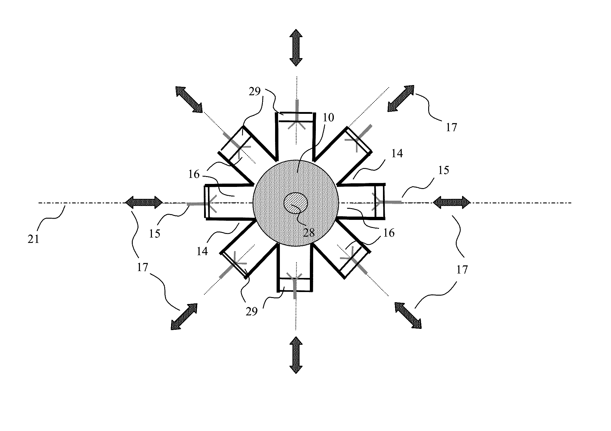
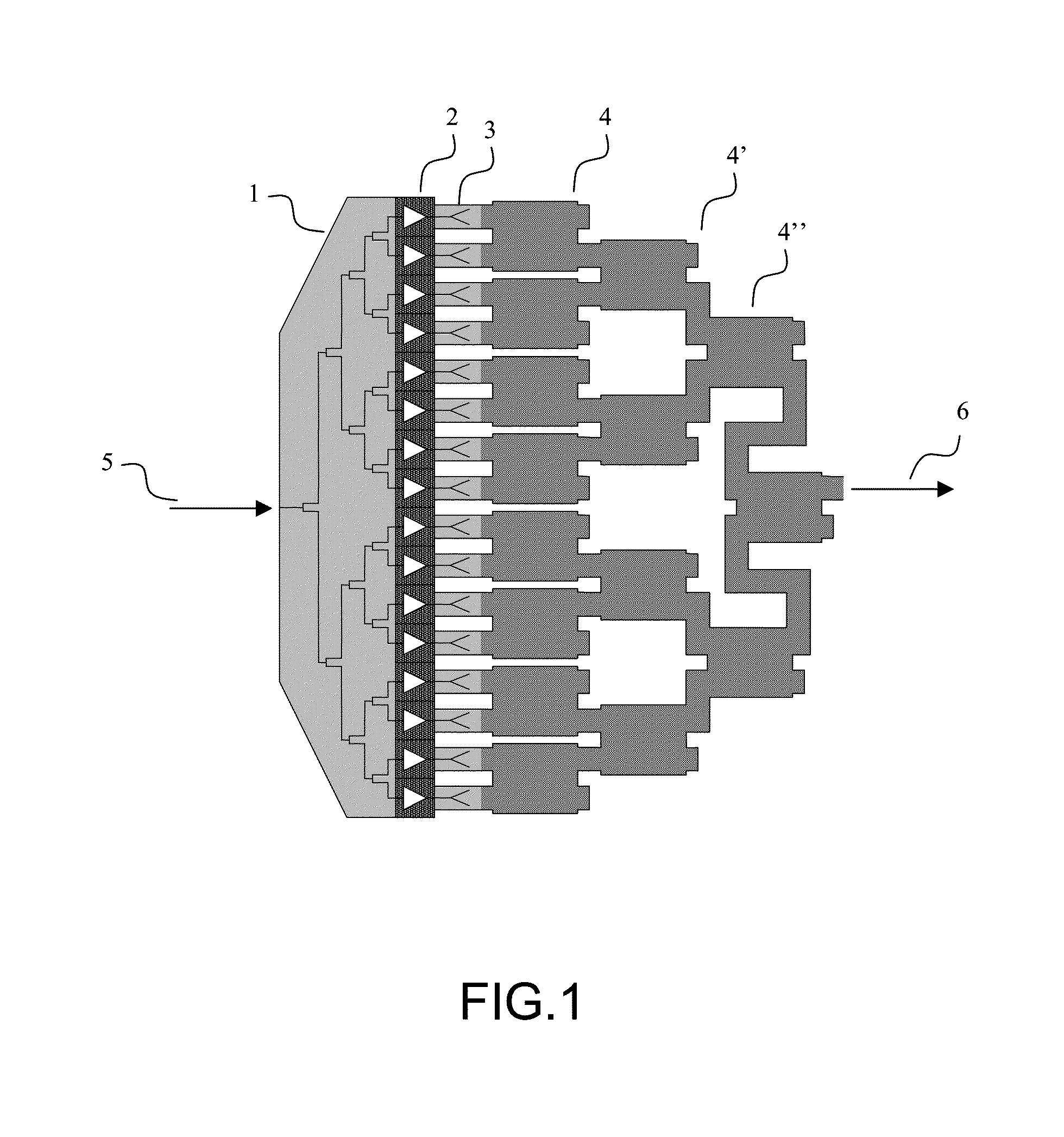
[0060]In the following description, a “transition” is any device which allows the transition of an electromagnetic wave from one propagation structure to another with the minimum of transmission losses such as, for example, a coaxial line to a radial waveguide, or a rectangular waveguide to one or more planar lines of the microwave strip type, coplanar, slot, or any other medium.

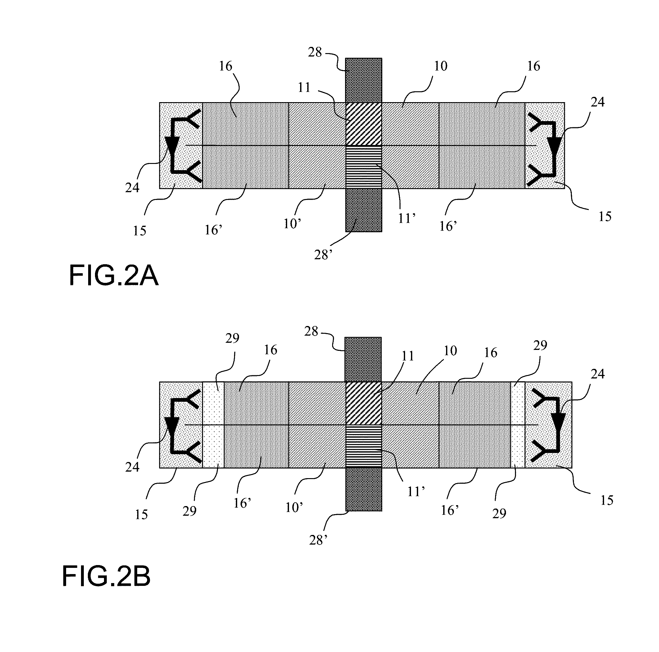
[0061]FIGS. 2A and 2B illustrate a representation in the form of blocks in a section through a device of the prior art and of an amplification device according to the invention, respectively.

[0062]The device comprises a divider containing a first radial waveguide 10 which an input signal enters by means of a transition 11, the transition 11 propagating the signal between a port 28, of the coaxial waveguide, cylindrical waveguide or rectangular waveguide type, for example, and the radial waveguide 10.

[0063]The divider of the amplification device comprises, in the example of FIG. 2B, a radial waveguide 10 with...


PUM


Abstract

A radial power combination system is provided. The system comprises a radial divider comprising ports in the form of rectangular waveguides on the periphery, a radial combiner superposed on the radial divider, comprising ports in the form of rectangular waveguides on the periphery, a first, input transition transmitting a first signal to the center of the radial divider, a second, output transition capturing the first signal amplified to the output of the radial combiner, at least two amplifying channels comprising a third, input transition capable of interacting with the guides, a fourth, output transition capable of interacting with the guides and at least one amplifier, and means for adjusting the positioning of the amplifying channels, thus making it possible to adjust the phase shift of the various channels.

Description

CROSS-REFERENCE TO RELATED APPLICATIONS[0001]This application is a National Stage of International Patent Application No. PCT / EP2008 / 067546, filed on Dec. 15, 2008, which claims priority to foreign Patent Application No. FR 07 08848, filed on Dec. 18, 2007, the disclosures of which are incorporated herein by reference in their entirety.FIELD OF THE INVENTION[0002]The present invention relates to the field of microwave amplifiers with semiconductors and more particularly power combination systems. Amongst the various combination techniques, the field of the invention is situated in the systems of radial power combinations.[0003]Since the output power of semiconducting elements reduces with the increase in operating frequency, it is necessary to combine several individual semiconducting amplifiers in order to achieve the output powers required by certain applications such as telemetry transmitters of high bit rate instruments of satellites for example.BACKGROUND OF THE INVENTION[0004]...

Claims


Application Information

Patent Timeline
Patent Type & Authority Patents(United States)
IPC IPC(8): H03F3/60
CPCH01P5/12H03F3/602
Inventor FRAYSSE, JEAN-PHILIPPEDENOUAL, JEAN-MICHELPEDEN, ALAIN
Owner THALES SA
Why Eureka
Try Eureka