Display control device

a control device and display technology, applied in the field of display control devices, can solve the problems of increasing unnecessarily long liquid crystal display, and the delay from the end of image data preparation, so as to prevent the delay, eliminate the distortion, and the effect of reducing the distortion

Active Publication Date: 2013-10-15
SEIKO EPSON CORP
View PDF10 Cites 5 Cited by
  • Summary
  • Abstract
  • Description
  • Claims
  • Application Information

AI Technical Summary

Benefits of technology

[0009]With the foregoing aspects of the prior art in view, it is an object of the present invention to shorten the display delay when the time required to prepare image data varies by predetermined data units.
[0010]To achieve this object, according to a first aspect of the present invention, an image data generating section performs generation processing for generating image data in a predetermined processing sequence for individual predetermined data units. A control section causes a display processing to be performed for a plurality of predetermined data units using a shared processing sequence when the process of generating the image data ends. The control section is configured to control the display unit so that the longer a first time relating to the generation processing for one of the predetermined data units of the image data is, the longer a second time until the display processing starts for the one of the predetermined data units of the image data is. The first time may be a time from an end of the generation processing for an Nth predetermined data unit (N is a natural number) in the processing sequence to an end of the generation processing for the (N+1)th predetermined data unit in the processing sequence, and the second time may be a time from an end of the generation processing for the Nth predetermined data unit to the start of the display processing for said (N+1)th predetermined data unit. This configuration can increase the delay from the end of the generation processing to the start of the display processing of image data by just the amount required for a predetermined data unit requiring a long time to prepare image data when the time required to prepare image data varies by predetermined data units.
[0013]The effect is greater when more time is required to prepare image data varies by predetermined data units. This is because a delay can be prevented based on the difference in the predetermined data units of the time required to prepare image data. An example of a process for varying the time required to prepare image data according to predetermined data units is a process performed using data generated in a previous step for the predetermined data units of the previous step, and using the data for a number of predetermined data units of the previous step according to the location of the predetermined data units to be processes. Due to the varying in the wait time until data to be used according to the number of predetermined data units in the previous step have been prepared, the time required to prepare image data differs according to the location; i.e., N, of the predetermined data units to be processed. A more specific example of a process for varying the time required to prepare image data by predetermined data units is distortion correction to eliminate distortion. This distortion correction generates image data for individual predetermined data units based on output data acquired from an image-capturing sensor (for example, an area image sensor), and varies the volume of output data required according to the location of each predetermined data unit. Specifically, the time required to prepare image data is varied by predetermined data units to vary the wait time until the required output data have been supplied according to the locations of the predetermined data units. This is because distortion is strongly dependent on the location in an image, and a larger range of images in the image-capturing sensor is required for a predetermined data unit located where there is greater distortion. The first time may include a variable time required for the generation processing and a predetermined invariable time, and may have a predetermined tendency according to the value of N. The second time may also have a predetermined tendency according to the value of N.
[0014]An image data generating section may carry out a generation processing for varying the time required according to how frequently an image representing a predetermined data unit is updated. Between a first image and a second image with a higher update frequency than the first image, preparing image data for a predetermined data unit indicating the second image takes more time. This is because of the high probability that new image data must be generated for a second image with a higher update frequency. For a first image with a low update frequency, on the other hand, the time to prepare image data is shorter because of the high probability that image data already generated need just be read from a memory. Therefore, the time required to prepare image data when synthesizing a first image with a second image varies between a predetermined data unit containing just the first image and a predetermined data unit containing the second image. If the first image and the second image are overlapped at set levels of transparency, the time required to prepare image data is longer for a predetermined data unit that contains overlapping pixels in which the second image is nontransparent (has less than 100% transparency).
[0016]When computer graphics are displayed, a background image with relatively little movement and an object with a lot of movement are depicted separately before an image depicting the object against the background image is synthesized. In this case, the image depicting an object with a lot of movement is the second image with a higher update frequency, and the time required to prepare image data for a predetermined data unit containing the second image is especially increased when the object depicted is a three-dimensional object. In this case as well, the display control device as described above can start the display processing earlier for a predetermined data unit containing only a first image with a short time required to prepare image data. In particular, the present invention can be applied to achieve a display with high response when a computer game is displayed.

Problems solved by technology

Therefore, configurations in which the time required to prepare image data may vary by line have had the problem that the delay from ending preparation of image data to displaying the image data on a liquid crystal display is unnecessarily long for lines that require a short time to prepare image data.
This configuration can increase the delay from the end of the generation processing to the start of the display processing of image data by just the amount required for a predetermined data unit requiring a long time to prepare image data when the time required to prepare image data varies by predetermined data units.
This is because distortion is strongly dependent on the location in an image, and a larger range of images in the image-capturing sensor is required for a predetermined data unit located where there is greater distortion.

Method used


Image

  • Display control device
  • Display control device
  • Display control device

Examples


Embodiment Construction

[0028]Preferred embodiments of the present invention will be described hereinafter in the following order: (1) Configuration of Image-capturing device; (2) Control of Horizontal Synchronization Signal; and (3) Other Embodiments.

(1) Configuration of Image-Capturing Device

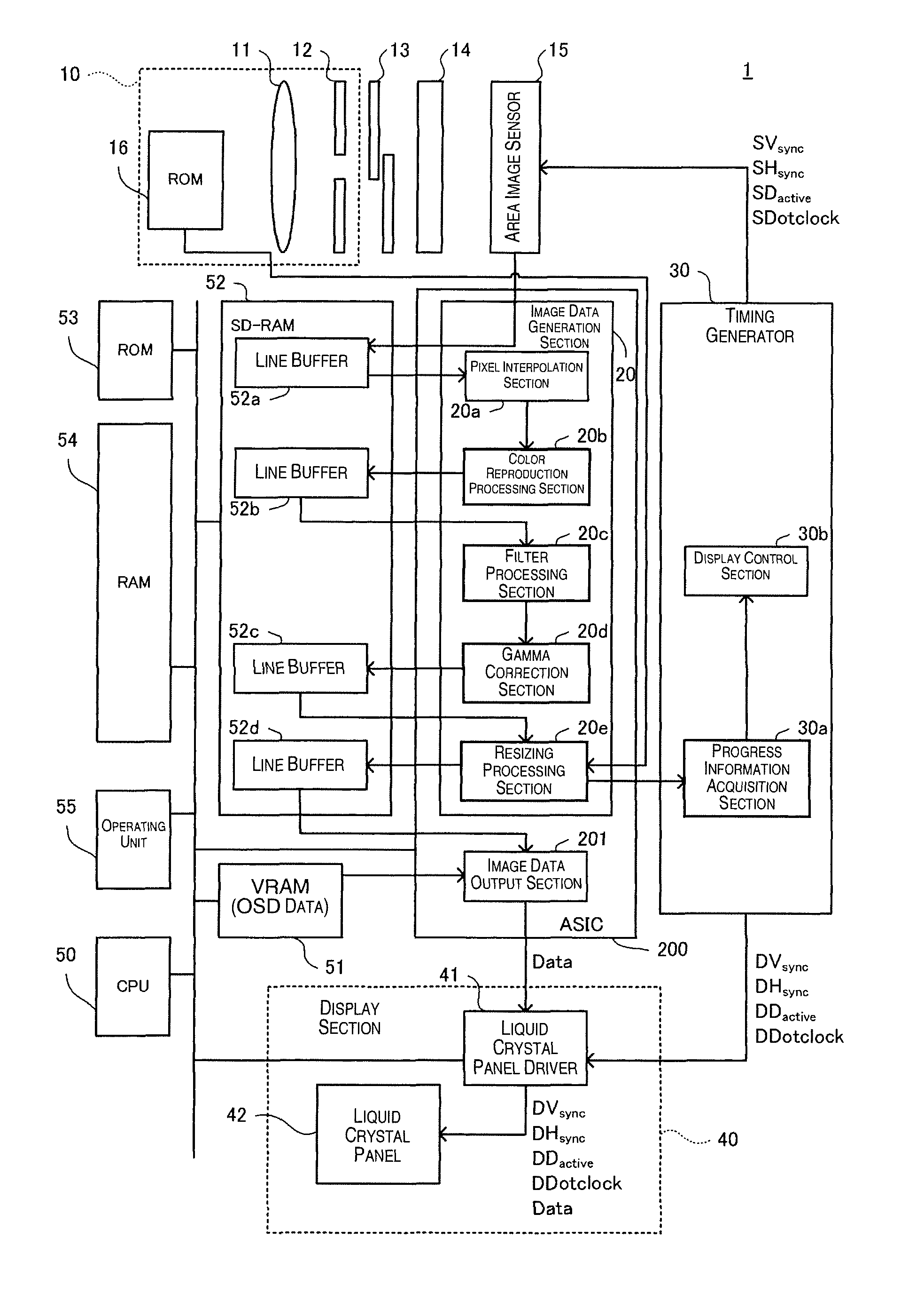
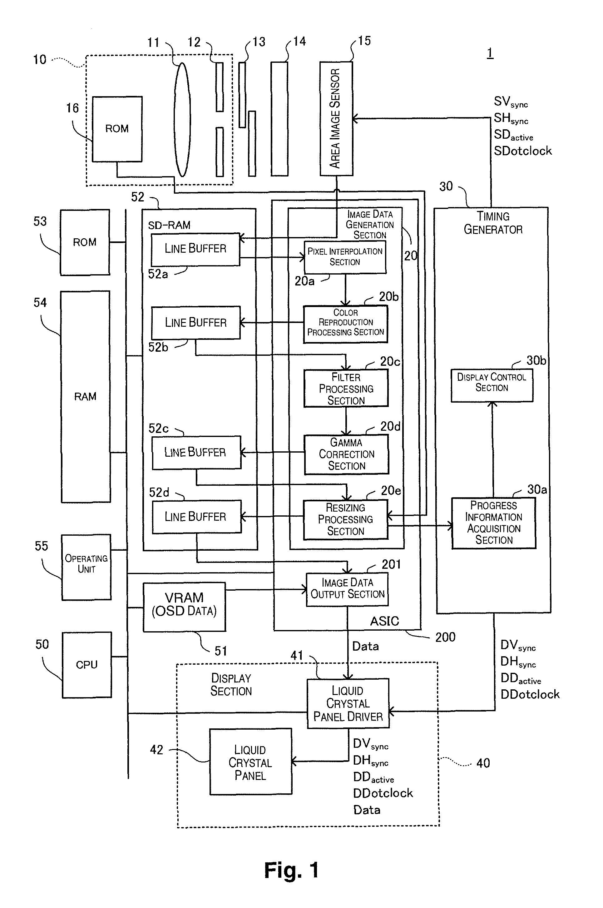
[0029]In FIG. 1, an image-capturing device 1 including a display control device according to an embodiment of the present invention has an interchangeable lens unit 10, a shutter 13, a low pass filter 14, an area image sensor 15 (corresponding to the image-capturing section), an ASIC 200, a timing generator 30, a display unit 40, a CPU 50, a VRAM 51, an SD-RAM 52, a ROM 53, a RAM 54, and an operating unit 55. The CPU 50 can use the VRAM 51, the SD-RAM 52, and the RAM 54 as appropriate to execute a program recorded in the ROM 53. Using this program, the CPU 50 executes a function for generating image data indicating a subject imaged by the area image sensor 15 according to an operation by the operating unit 55. The op...


PUM


Abstract

A display control device includes an image data generating section and a control section. The image data generating section is configured to perform generation processing for generating image data in a predetermined processing sequence for each of a plurality of predetermined data units of the image data. The control section is configured to control a display unit to execute display processing based on the image data in the processing sequence for each of the predetermined data units. The control section is configured to control the display unit so that the longer a first time relating to the generation processing for one of the predetermined data units of the image data is, the longer a second time until the display processing starts for the one of the predetermined data units of the image data is.

Description

CROSS-REFERENCE TO RELATED APPLICATIONS[0001]This application claims priority to Japanese Patent Application No. 2010-125568 filed on Jun. 1, 2010. The entire disclosure of Japanese Patent Application No. 2010-125568 is hereby incorporated herein by reference.BACKGROUND[0002]1. Technical Field[0003]The present invention relates to a display control device for displaying by predetermined data units.[0004]2. Related Art[0005]Pickup devices for displaying an image picked up by an image sensor on a liquid crystal display have been known in the art, and techniques have been developed to prevent delaying an image to be displayed on a liquid crystal display relative to the actual subject. For example, Japanese Laid-Open Patent Application Publication No. 2007-243615 has disclosed a technique for reading and displaying an image signal on a liquid crystal display before writing the image signal of one frame on a VRAM has ended in an image-capturing device having a VRAM for recording an image...

Claims


Application Information

Patent Timeline
Patent Type & Authority Patents(United States)
IPC IPC(8): H04N5/228H04N5/222H03L7/00
CPCG06T1/00G09G3/3611G09G3/36H04N5/23293H04N5/357H04N23/663H04N23/951H04N23/80H04N23/63H04N25/60H04N25/61H04N25/134G06T5/002G06T2207/10004
Inventor SHIOHARA, RYUICHI
Owner SEIKO EPSON CORP
Why Eureka
Try Eureka