
Leakage detection system in a wind turbine

a leakage detection and wind turbine technology, applied in the direction of rotary clutches, couplings, fluid couplings, etc., can solve the problems of high amount of oil already leaked, high amount of oil may leak out of the hydraulic device, etc., and achieve the effect of fast leakage detection

Active Publication Date: 2013-10-22
SIEMENS GAMESA RENEWABLE ENERGY AS
View PDF7 Cites 8 Cited by
  • Summary
  • Abstract
  • Description
  • Claims
  • Application Information

AI Technical Summary

Benefits of technology

Enables continuous monitoring and immediate leakage detection, reducing oil loss by comparing measured fluid levels with calculated volumes and providing accurate alarms, thus enhancing operational control and reducing false alarms in wind turbine hydraulic systems.

Problems solved by technology

If a leakage turns up in the hydraulic system, in particular at outside located hydraulic devices with a large distance from to the oil tank, a high amount of oil may leak out from the hydraulic device before the oil level sensor may measure the leakage based on recirculation of the hydraulic fluid.
In the time period between the beginning of the leakage and the alarm initiation a high amount of oil may be already leaked.

Method used


Image

  • Leakage detection system in a wind turbine
  • Leakage detection system in a wind turbine
  • Leakage detection system in a wind turbine

Examples


Embodiment Construction

[0035]The illustrations in the drawings are schematically. It is noted that in different figures, similar or identical elements are provided with the same reference signs.

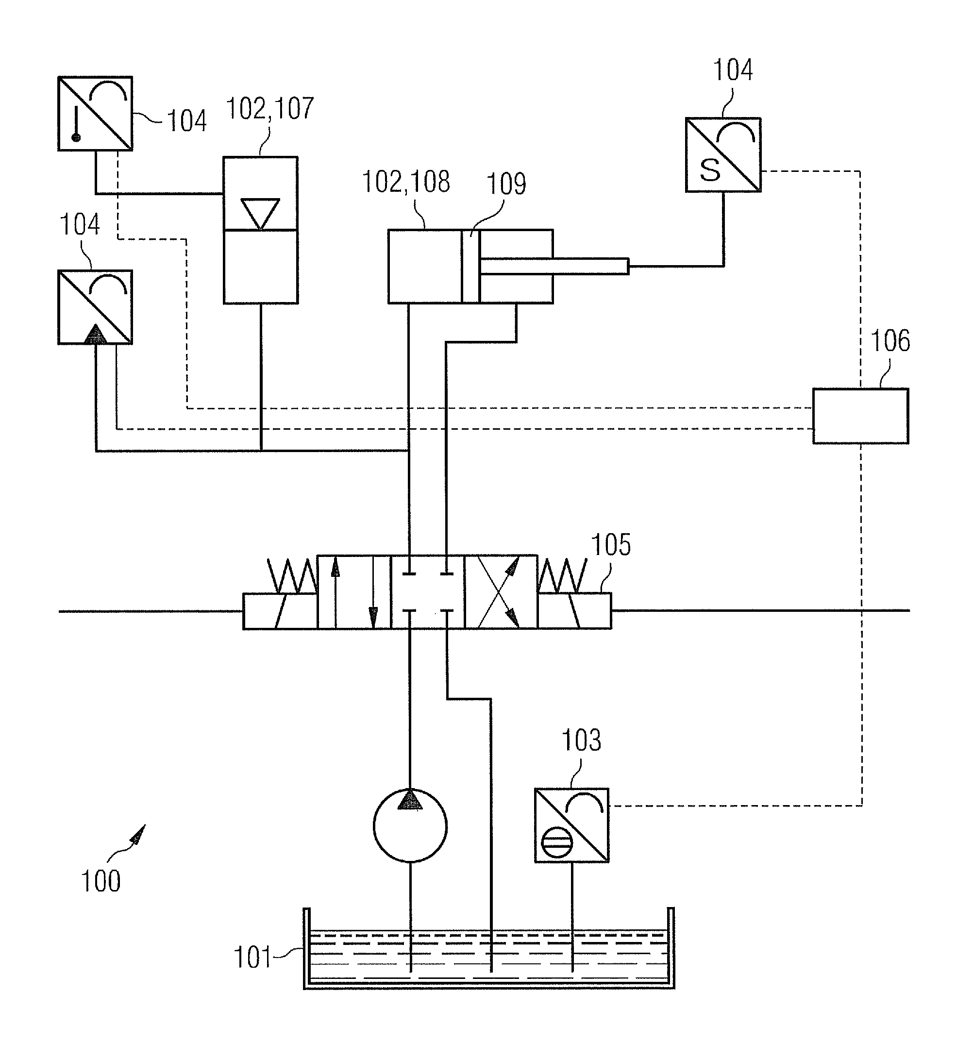
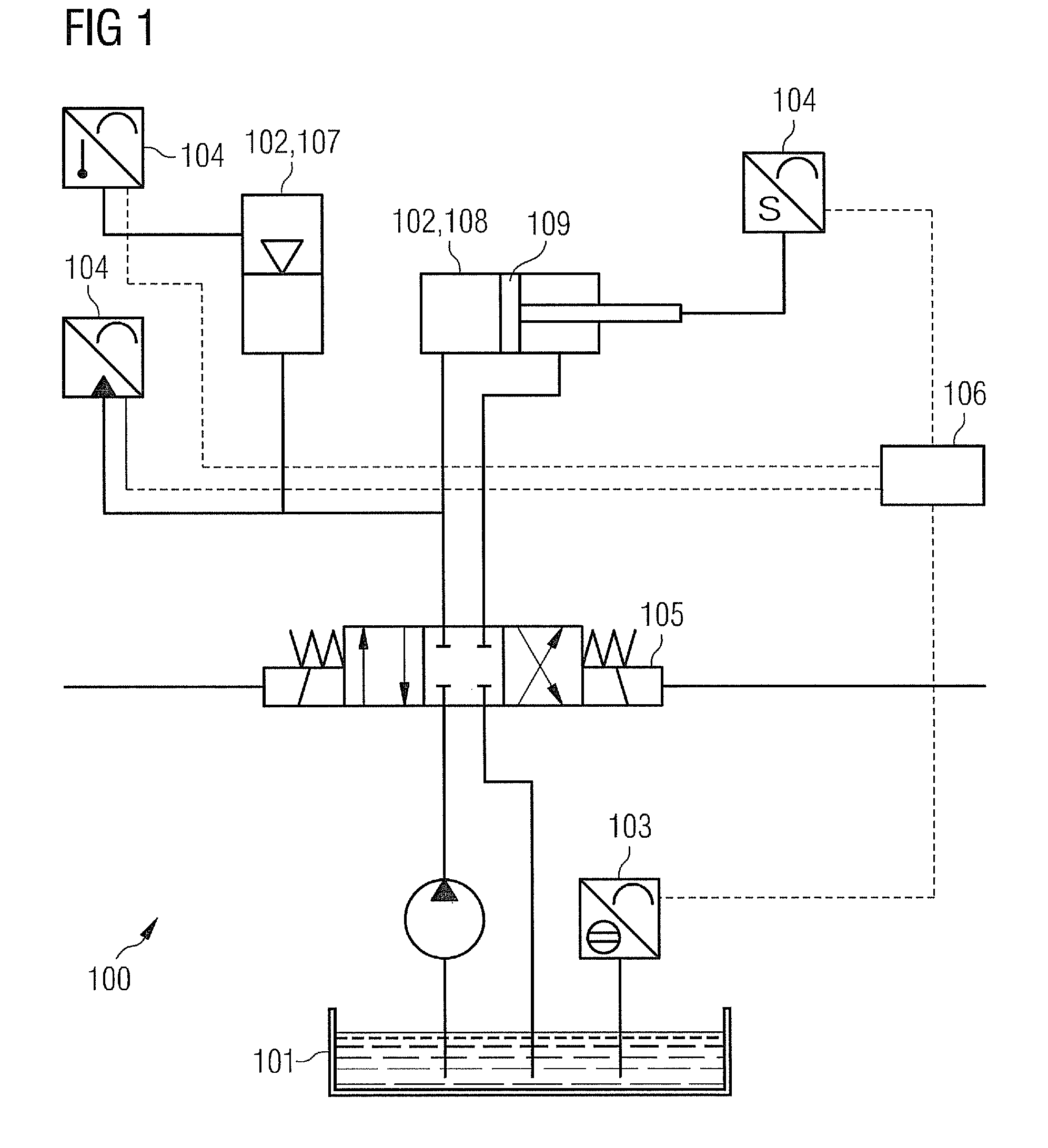
[0036]FIG. 1 illustrates a hydraulic system 100. The hydraulic system 100 comprises a reservoir 101, a hydraulic device 102, a first sensor 103, a second sensor 104 and a controller 106. The reservoir 101 is connected to the hydraulic device 102 for supplying hydraulic fluid to and / or from the hydraulic device 102. The first sensor 103 is adapted for measuring a first volume V1 of the hydraulic fluid in the reservoir 101. The second sensor 104 is connected to the hydraulic device 102 in such a way that at least one parameter being indicative for a second volume V2 of the hydraulic fluid in the hydraulic device 102 is measurable. The controller 106 is adapted for calculating the second volume V2 of the hydraulic fluid based on the at least one parameter. Moreover, the controller 106 is adapted for determining a leak...


PUM


Abstract

In one aspect, a hydraulic system including a reservoir, a hydraulic device, a first sensor, a second sensor and a controller is described. The reservoir is connected to the hydraulic device for supplying hydraulic fluid to and from the hydraulic device. The first sensor is adapted for measuring a first volume of the hydraulic fluid in the reservoir. The second sensor is connected to the hydraulic device such that at least one parameter being indicative for a second volume of the hydraulic fluid in the hydraulic device is measurable. The controller is adapted for calculating the second volume of the hydraulic fluid based on the at least one parameter. The controller is adapted for determining a leakage of hydraulic fluid in the hydraulic system based on the first volume and the second volume.

Description

CROSS REFERENCE TO RELATED APPLICATIONS[0001]This application claims priority of European Patent Office application No. 09008159.7 EP filed Jun. 22, 2009, which is incorporated by reference herein in its entirety.FIELD OF INVENTION[0002]The present invention relates to a hydraulic system and a wind turbine. Moreover, the invention relates to a method for determining a leakage of a hydraulic fluid in a hydraulic system.ART BACKGROUND[0003]Today, systems in wind turbines for controlling and operating the wind turbine are based on hydraulic systems. In particular, a pitch servo system and a brake system of a wind turbine may be based on hydraulic systems and components.[0004]In the nacelle of the wind turbine a hydraulic fluid tank or a reservoir and a pump station is installed for supplying the hydraulic fluid to the hydraulic devices. The hydraulic fluid, e.g. hydraulic oil, is pumped to the installation locations of the hydraulic systems and hydraulic components. In particular, the ...

Claims


Application Information

Patent Timeline
Patent Type & Authority Patents(United States)
IPC IPC(8): F16D37/00
CPCF15B19/005F16N19/003F05B2260/80F15B2211/6306F15B2211/6336F15B2211/6343F15B2211/665Y02E10/72
Inventor EGEDAL, PERMUNCH, JESPER
Owner SIEMENS GAMESA RENEWABLE ENERGY AS
Learn More