Hydraulic system for working vehicle

a technology for working vehicles and hydraulic systems, which is applied in the direction of mechanical actuated clutches, machines/engines, distribution equipment, etc., can solve the problems of preventing insufficient amount of lubricating oil in the transmission device, affecting the so as to reduce the variance in efficiency, prevent the effect of variance in efficiency of high-pressure pumps

a technology for working vehicles and hydraulic systems, which is applied in the direction of mechanical actuated clutches, machines/engines, distribution equipment, etc., can solve the problems of preventing insufficient amount of lubricating oil in the transmission device, affecting the so as to reduce the variance in efficiency, prevent the effect of variance in efficiency of high-pressure pumps

US8561760B2Active Publication Date: 2013-10-22KOMATSU LTD

Image

  • Hydraulic system for working vehicle
  • Hydraulic system for working vehicle
  • Hydraulic system for working vehicle

Examples


Embodiment Construction

Structure of Bulldozer

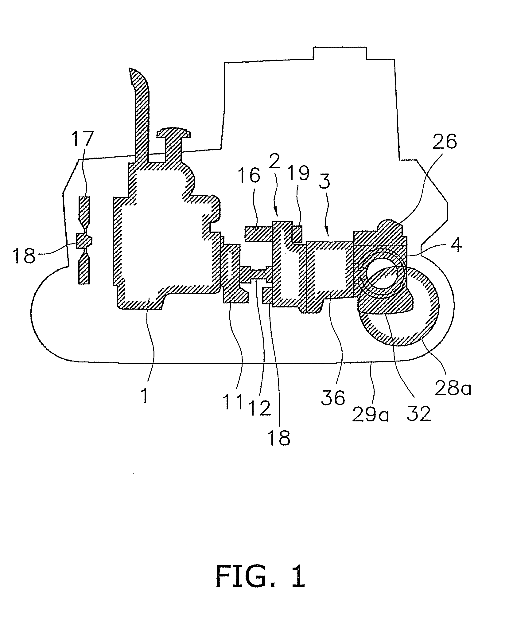
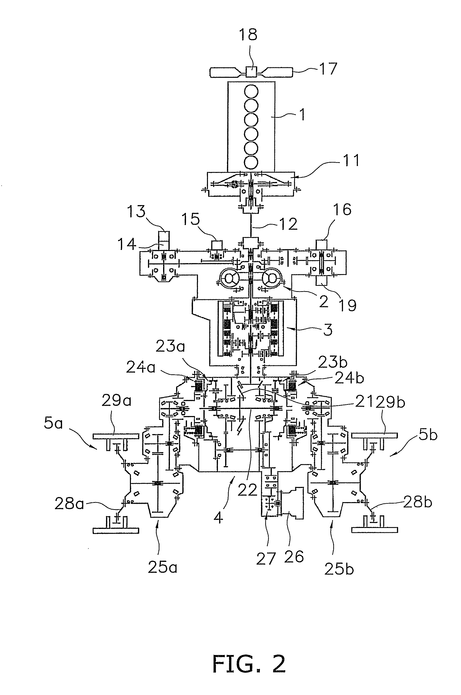
[0019]The structure of a bulldozer provided with the hydraulic system according to an embodiment of the present invention is shown in FIGS. 1 and 2. This bulldozer comprises an engine 1, a torque converter 2, a transmission device 3, a steering device 4, and a pair of travel devices 5a, 5b (see FIG. 2).

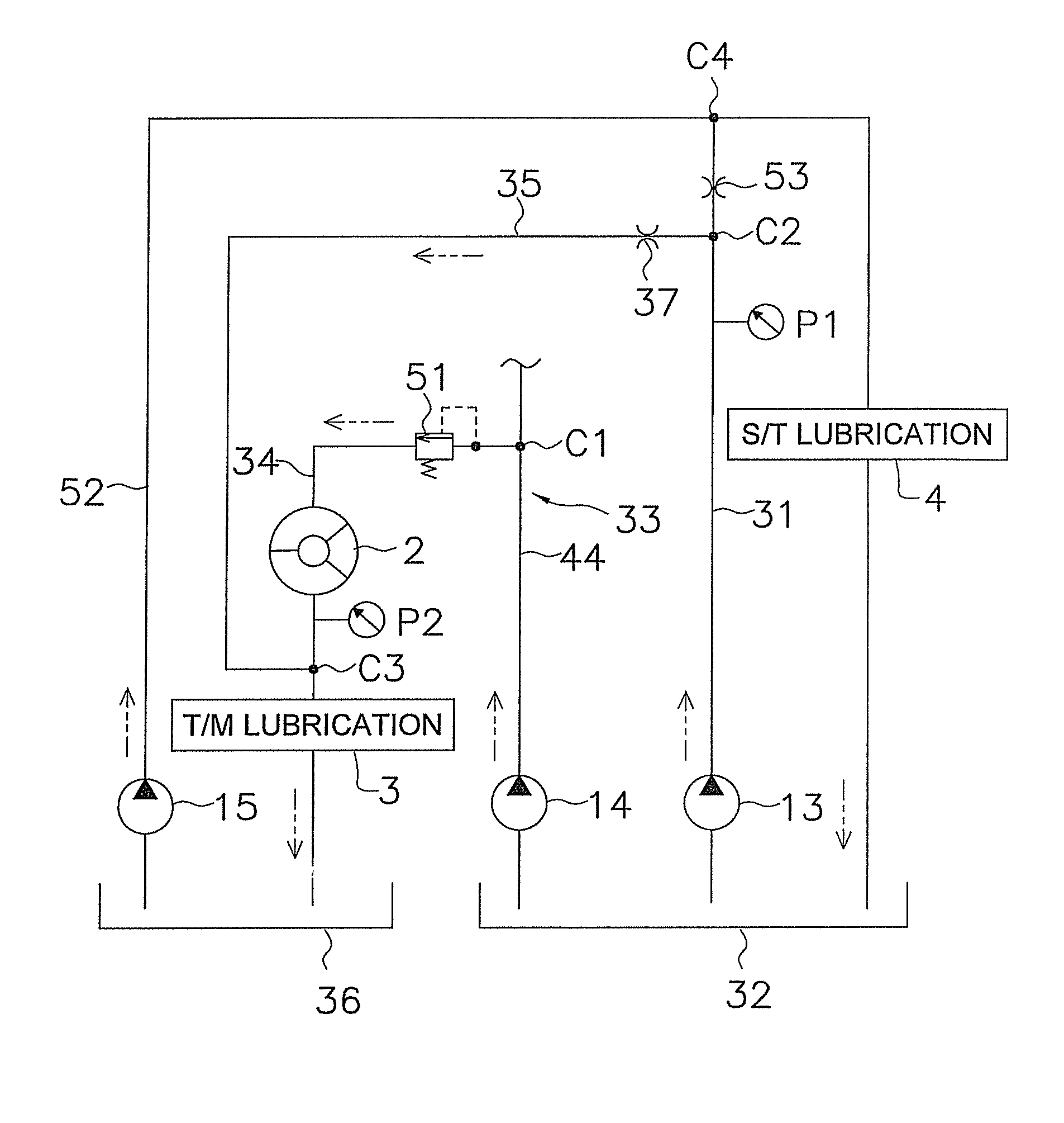
[0020]The engine 1 is a diesel engine, and the output of the engine 1 is controlled by adjusting the amount of fuel injected from a fuel injection pump (not shown). The power generated by the engine 1 is transmitted to the torque converter 2 via a damper 11 and a universal joint 12. Furthermore, the engine drives a low-pressure pump 13, a high-pressure pump 14, a scavenging pump 15, a steering pump 16, a cooling fan pump 19, which are described below, and other hydraulic pumps. Additionally, a cooling fan 17 and a cooling fan motor 18 are provided in front of the engine 1. The cooling fan motor 18 is driven by oil from the cooling fan pump 19.

[0021]The torque con...


PUM


Abstract

A low-pressure pump supplies oil stored in a steering case to a steering device as lubricating oil via a steering lubricating circuit. A high-pressure pump supplies the oil stored in the steering case to a clutch via a high-pressure circuit. A transmission lubricating circuit branches off from the high-pressure circuit via a relief valve and supplies lubricating oil to a transmission device. A transmission-lubricating assist circuit is provided so as to branch off from the steering lubricating circuit and is connected to the transmission lubricating circuit. A transmission case stores the oil used to lubricate the transmission device. A scavenging pump returns the oil stored in the transmission case to the steering device.

Description

CROSS-REFERENCE TO RELATED APPLICATIONS[0001]This national phase application claims priority to Japanese Patent Application No. 2009-017879 filed on Jan. 29, 2009. The entire disclosure of Japanese Patent Application No. 2009-017879 is hereby incorporated herein by reference.TECHNICAL FIELD[0002]The present invention relates to a hydraulic system for a working vehicle, and particularly to a hydraulic system for supplying lubricating oil to a transmission device and a steering device.BACKGROUND ART[0003]In a working vehicle such as a bulldozer, lubricating oil is supplied to the transmission device and the steering device. The lubricating oil supplied to the transmission device and the steering device is recovered in a transmission case for housing the transmission device and a steering case for housing the steering device, respectively, and is reused (see Japanese Laid-Open Patent Publication No. 2004-211665).[0004]The structure of a conventional hydraulic system for supplying lubri...

Claims


Application Information

Patent Timeline
22 Oct 2013
Publication
US8561760B2
IPC
F01M1/00; F16N25/00; F16H57/02; F16H57/04
CPC
F16H61/0021; F16H57/0436; F16H57/0445; F16H2061/0037; F16H57/0446
Inventors
YOSHIKAWA, TAKESHI; MIYAMOTO, HITOSHI