Hydraulic system for working vehicle

Active Publication Date: 2011-11-10
KOMATSU LTD
View PDF12 Cites 17 Cited by
  • Summary
  • Abstract
  • Description
  • Claims
  • Application Information

AI Technical Summary

Benefits of technology

[0010]In this hydraulic system, oil that is discharged from the low-pressure pump is supplied to the transmission lubricating circuit via the transmission-lubricating assist circuit. The oil is then combined with the oil discharged from the high-pressure pump, and is supplied as the lubricating oil to the transmission device. The low-pressure pump has less variance in efficiency in comparison with the high-pressure pump. Poor lubrication of the transmission device caused by variance in efficiency of the high-pressure pump is therefore preventable. Furthermore, because the high-pressure pump does not need to be enlarged, increase in production cost is preventable. Additionally, a portion of the oil discharged from the low-pressure pump is sent to the transmission lubricating circuit via the transmission-lubricating assist circuit, and is eventually returned to the steering device by the scavenging pump. Reduction in the amount of lubricating oil in the steering device is therefore also preventable.
[0011]The hydraulic system for a working vehicle according to a second aspect is the hydraulic system according to the first as

Problems solved by technology

Furthermore, the high-pressure pump has greater individual variance in efficiency compared with the low-pressure pump.
For this reason, such a hydraulic system has a possibility that the amount of lubricating oil in the transmission device may become insufficient in case the variance in efficiency of the high-pressure pump exceeds an allowable value.
On one hand, the insufficient amount of lubricating oil in the transmission device is preventable by using a high-pressure pump having surplus capacity.
In this case, however, the

Method used


Image

  • Hydraulic system for working vehicle
  • Hydraulic system for working vehicle
  • Hydraulic system for working vehicle

Examples


Embodiment Construction

Structure of Bulldozer

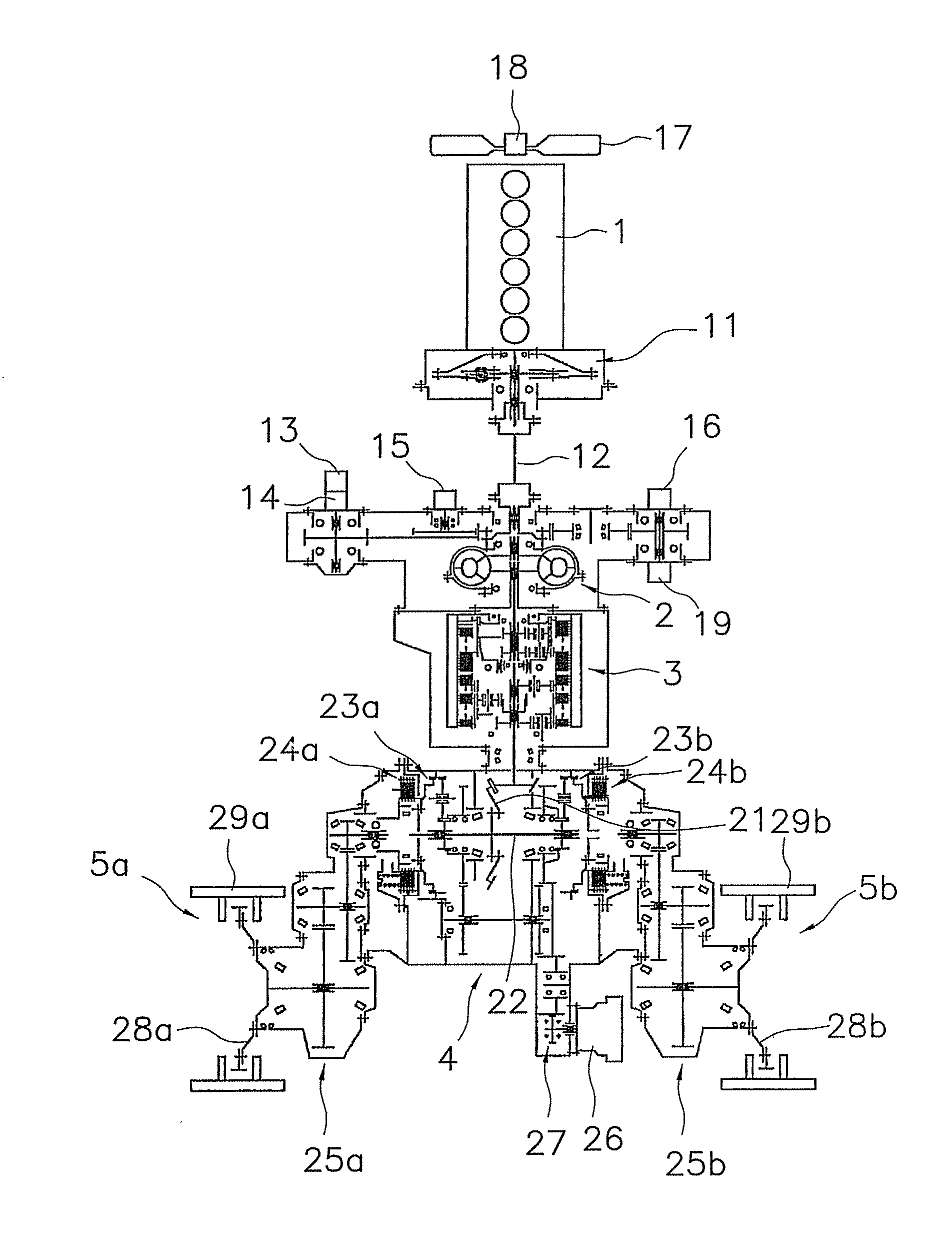
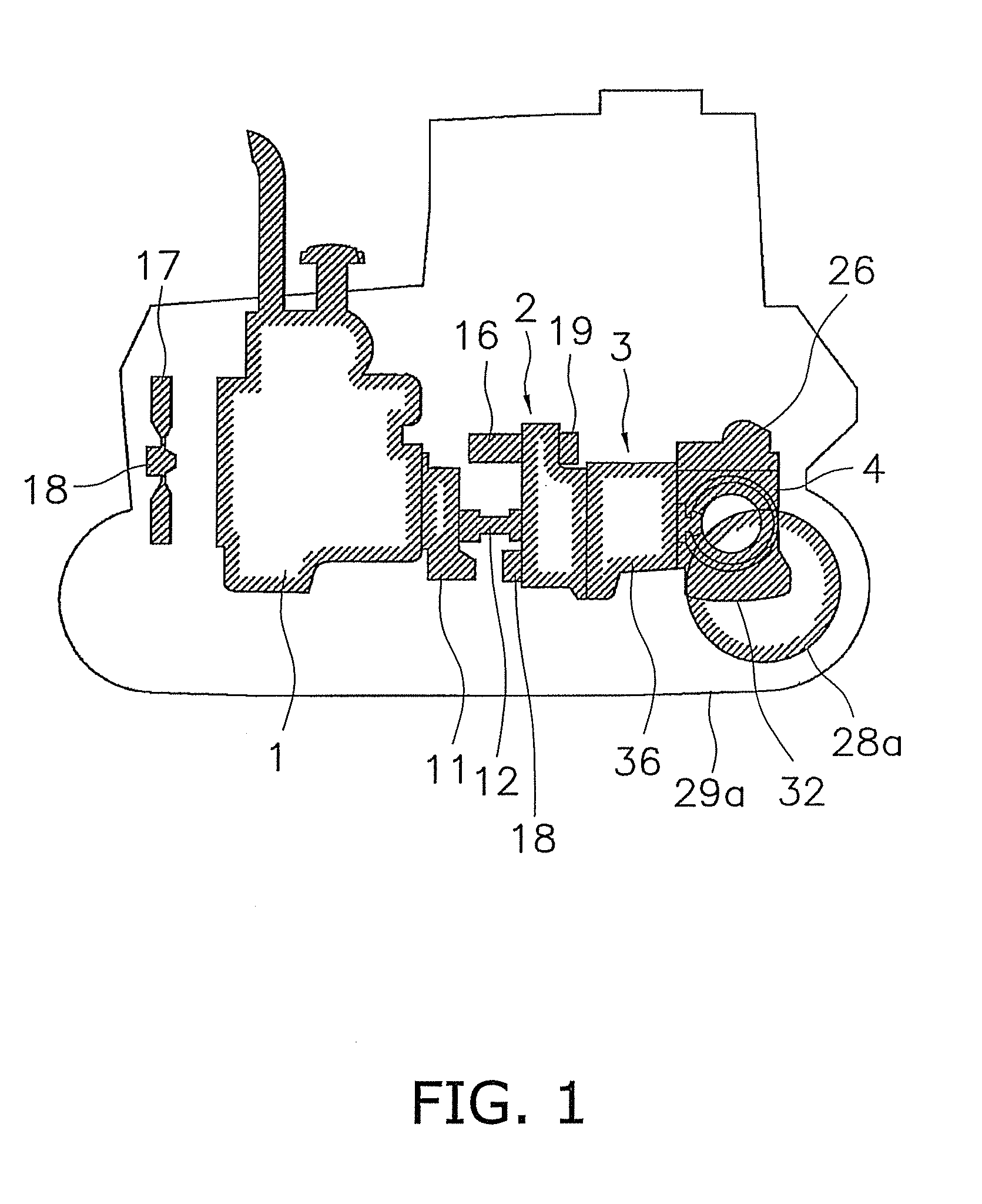
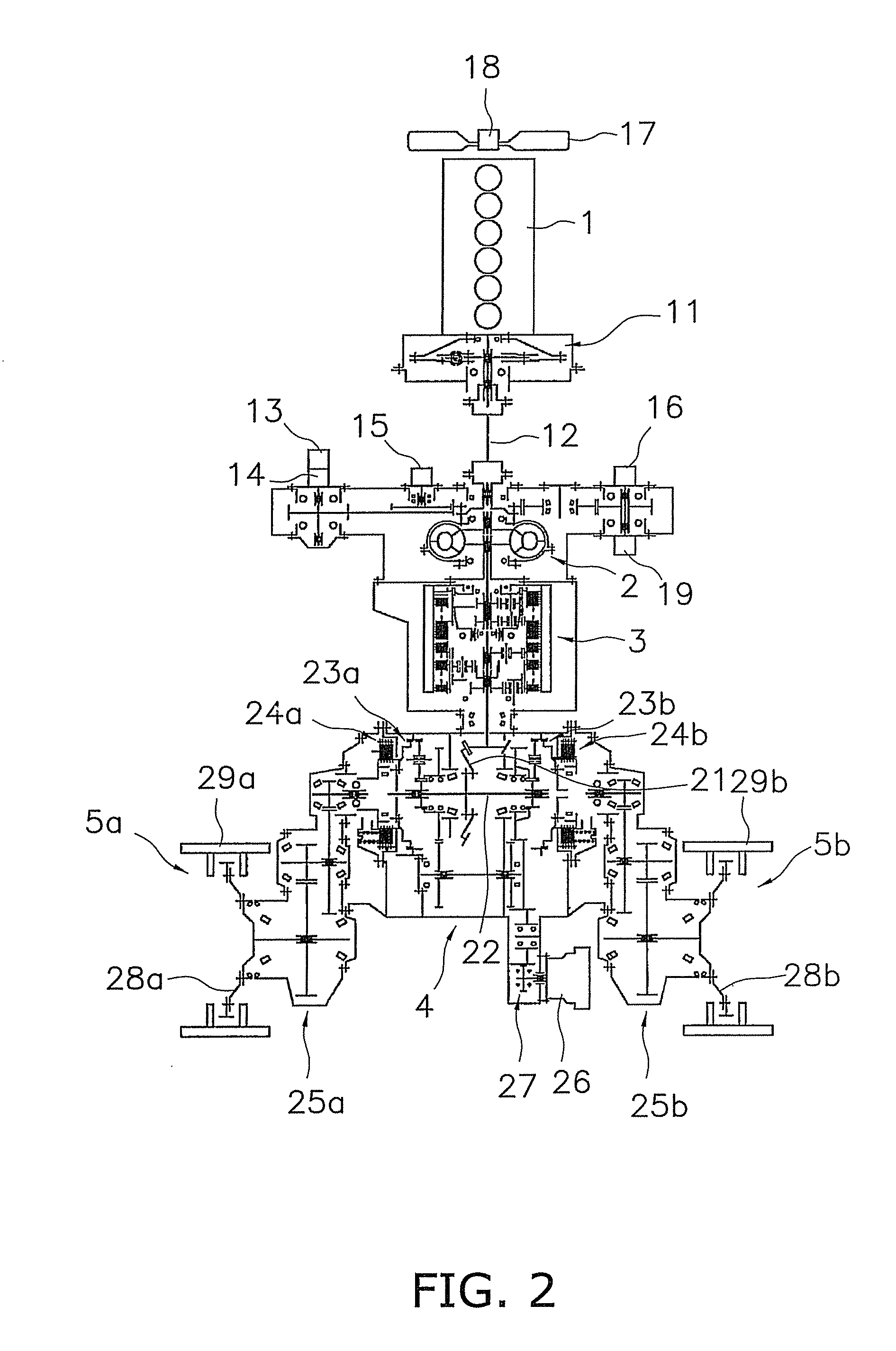
[0019]The structure of a bulldozer provided with the hydraulic system according to an embodiment of the present invention is shown in FIGS. 1 and 2. This bulldozer comprises an engine 1, a torque converter 2, a transmission device 3, a steering device 4, and a pair of travel devices 5a, 5b (see FIG. 2).

[0020]The engine 1 is a diesel engine, and the output of the engine 1 is controlled by adjusting the amount of fuel injected from a fuel injection pump (not shown). The power generated by the engine 1 is transmitted to the torque converter 2 via a damper 11 and a universal joint 12. Furthermore, the engine drives a low-pressure pump 13, a high-pressure pump 14, a scavenging pump 15, a steering pump 16, a cooling fan pump 19, which are described below, and other hydraulic pumps. Additionally, a cooling fan 17 and a cooling fan motor 18 are provided in front of the engine 1. The cooling fan motor 18 is driven by oil from the cooling fan pump 19.

[0021]The torque con...


PUM


Abstract

A low-pressure pump supplies oil stored in a steering case to a steering device as lubricating oil via a steering lubricating circuit. A high-pressure pump supplies the oil stored in the steering case to a clutch via a high-pressure circuit. A transmission lubricating circuit branches off from the high-pressure circuit via a relief valve and supplies lubricating oil to a transmission device. A transmission-lubricating assist circuit is provided so as to branch off from the steering lubricating circuit and is connected to the transmission lubricating circuit. A transmission case stores the oil used to lubricate the transmission device. A scavenging pump returns the oil stored in the transmission case to the steering device.

Description

CROSS-REFERENCE TO RELATED APPLICATIONS[0001]This national phase application claims priority to Japanese Patent Application No. 2009-017879 filed on Jan. 29, 2009. The entire disclosure of Japanese Patent Application No. 2009-017879 is hereby incorporated herein by reference.TECHNICAL FIELD[0002]The present invention relates to a hydraulic system for a working vehicle, and particularly to a hydraulic system for supplying lubricating oil to a transmission device and a steering device.BACKGROUND ART[0003]In a working vehicle such as a bulldozer, lubricating oil is supplied to the transmission device and the steering device. The lubricating oil supplied to the transmission device and the steering device is recovered in a transmission case for housing the transmission device and a steering case for housing the steering device, respectively, and is reused (see Japanese Laid-Open Patent Publication No. 2004-211665).[0004]The structure of a conventional hydraulic system for supplying lubri...

Claims


Application Information

Patent Timeline
IPC IPC(8): F16D13/74F16H57/02F16H57/04
CPCF16H57/0436F16H57/0445F16H57/0446F16H61/0021F16H2061/0037
Inventor YOSHIKAWA, TAKESHIMIYAMOTO, HITOSHI
Owner KOMATSU LTD
Why Eureka
Try Eureka