Bipolar high frequency treatment device

a high frequency treatment and bipolar technology, applied in the field of bipolar high frequency treatment devices, can solve the problems of short circuit or leakage of high frequency current, and achieve the effect of firmly and reliably fixing and safe operation of bipolar high frequency treatmen

Active Publication Date: 2013-10-22
KANEKA CORP
View PDF15 Cites 229 Cited by
  • Summary
  • Abstract
  • Description
  • Claims
  • Application Information

AI Technical Summary

Benefits of technology

[0017]According to this configuration, by making the separation element completely separate the first pivot support portion from the second pivot support portion, the bipolar high frequency treatment device can be provided, which can safely operate without causing a leakage or short-circuit of the high frequency current between the first forceps blade and the second forceps blade.
[0020]According to this configuration, the first supported portion and the first pivot support portion are formed in the shape of a continuous plate, and the second supported portion and the second pivot support portion are formed in the shape of a continuous plate, and the first grip portion and the first pivot support portion are integrally formed, and the second grip portion and the second pivot support portion are integrally formed, so that the first grip portion and the second grip portion can be closed so as to come face to face. Therefore, a safely operable bipolar high frequency treatment device can be provided, which is comprised by compactly fixing the first forceps blade and the second forceps blade into the support portion.
[0027]According to this configuration, the separation element provided at the ends of the side portions, which side portions extend from one end of the tube receiving portion and are formed in parallel with each other, is formed so as to have the central element separating the first receiving groove for receiving the first pivot support portion and the second receiving groove for receiving the second pivot support portion. Therefore, the pivoting movements of the first pivot support portion and the second pivot support portion in the first receiving groove and the second receiving groove are smoothly performed without becoming shaky. Moreover, there is neither a leakage nor short-circuit of the high frequency current between the first pivot support portion and the second pivot support portion separated by the central element, which results in a safely operable bipolar high frequency treatment device.
[0029]According to this configuration, since the first receiving groove is provided with the first opening-degree control portion and the second receiving groove is provided with the second opening-degree control portion, respectively, the first grip portion and the second grip portion are opened widely to such an extent that the first grip portion contacts the second pivot support portion and the second grip portion contacts the first pivot support portion, in such an manner that there is neither a leakage nor short-circuit of the high frequency current between the first grip portion and the second grip portion, which leads to a safely operable bipolar high frequency treatment device.
[0031]According to this configuration, since the whole support member is integrally formed, the strength of the whole support member can be increased.
[0037]According to this configuration, since the insulating separation member penetrates the catheter tube in the direction of the diameter thereof inside the catheter tube in the vicinity of the top end of the catheter tube having one through hole running from the top end to the rear end, the two wires allowing the high frequency current to flow can be separated, and the support member and the catheter tube can be firmly and reliably fixed by mechanical connection. Therefore, there is neither a leakage nor short-circuit of the high frequency current between the wires, and without disconnection of the catheter tube and the support member, a safely operable bipolar high frequency treatment device can be provided.

Problems solved by technology

Consequently, if the insulating distance is approximately 0.5 mm, it is not sufficient for the purpose of insulating, and there is a possibility of causing the short-circuit or a leakage of the high frequency current.
Then, in case the first forceps blade and the second forceps blade are attached to the top end portions of the pair of support elements, the attachment causes shaking or the first forceps blade and the second forceps blade are incapacitated to pivot smoothly because they are fastened too tight.
Consequently, for fear of such electrical contact, there arises an inconvenience that the first forceps blade and the second forceps blade cannot be opened to the fullest, and the first forceps blade and the second forceps blade cannot be widened so as to fit to the size of the lesion region existing in the body.

Method used


Image

  • Bipolar high frequency treatment device
  • Bipolar high frequency treatment device
  • Bipolar high frequency treatment device

Examples


first embodiment

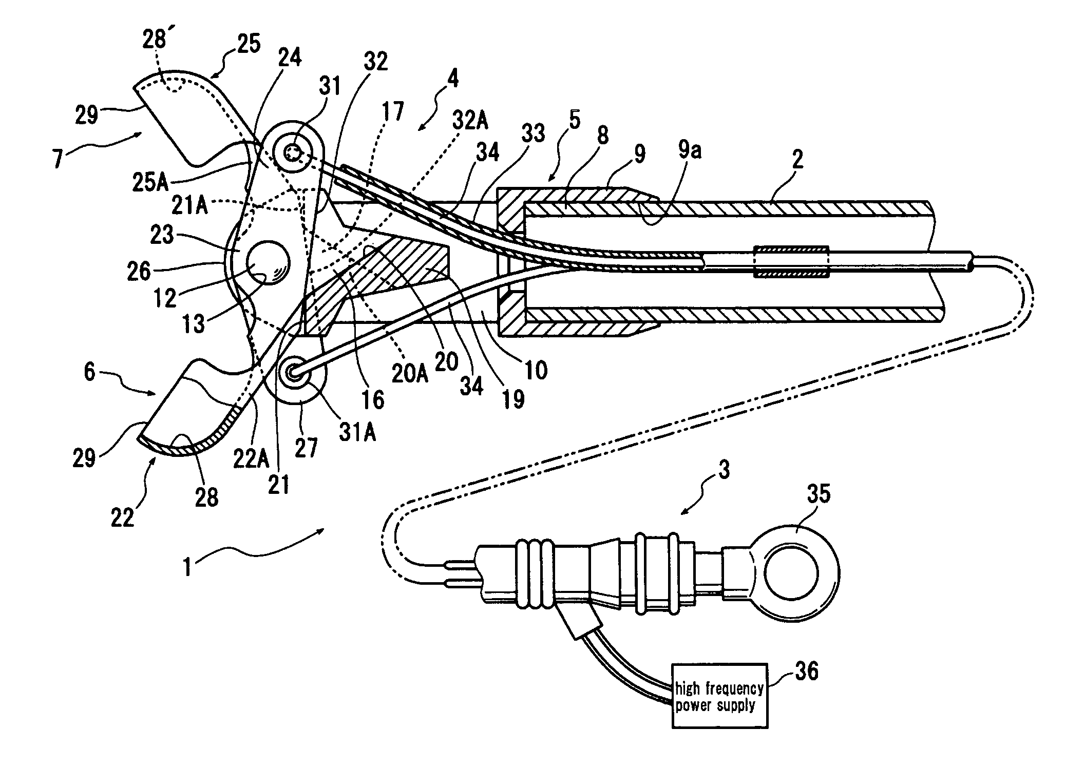
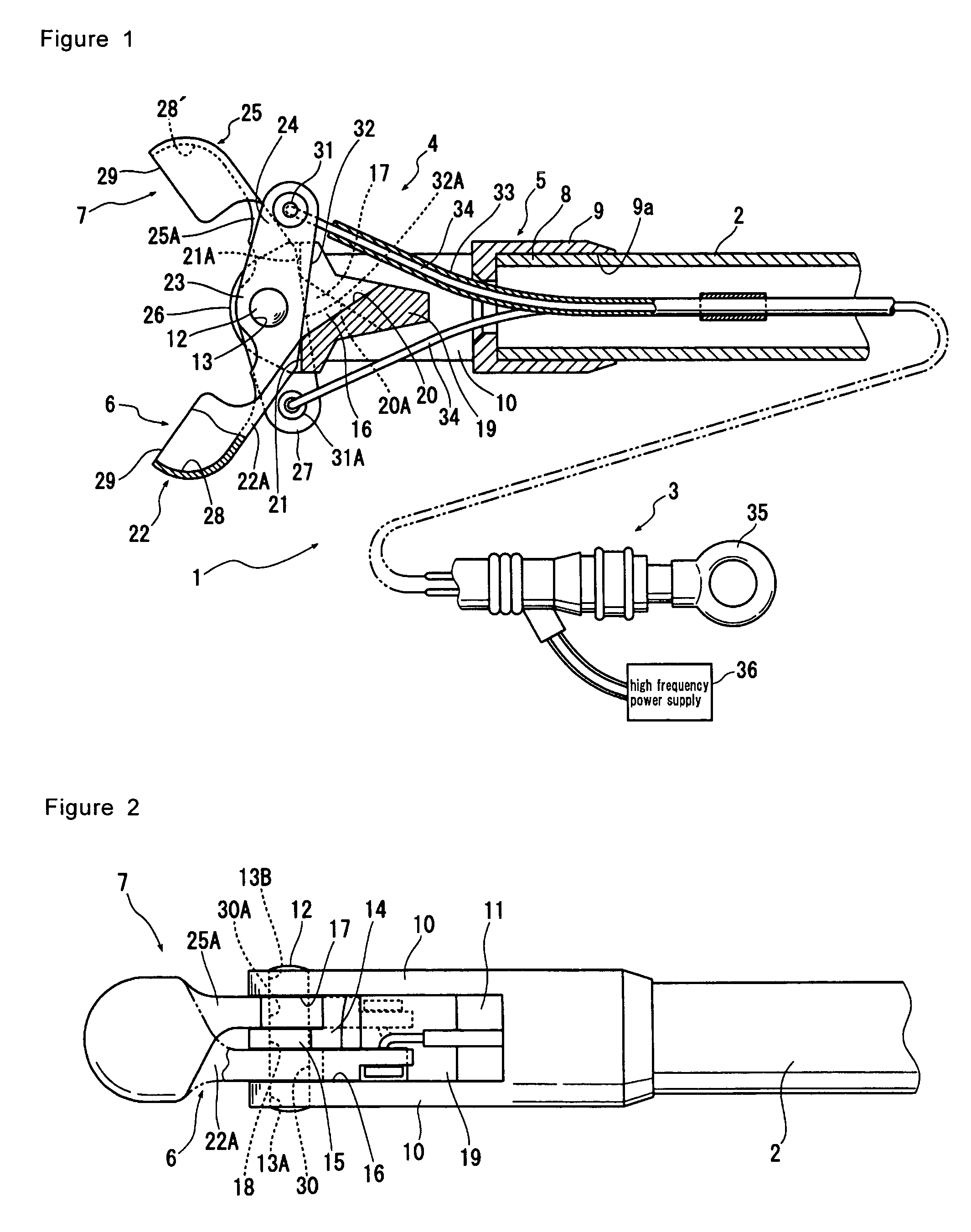
[0048]As shown in FIG. 1, a bipolar high frequency treatment device 1 according to the first embodiment of the present invention comprises a catheter tube 2, which is, for example, which can be inserted into a stomach and a large intestine in the body through a treatment device passage in an endoscope (not shown). This catheter tube 2 is made of a soft insulating material having flexibility. For the insulating material, for example, synthetic resins and the like, such as polyethylene, polypropylene, polyacetal, polyester, polyether sulfone, polyether ether ketone (PEEK), polyimide, fluorine-containing resins and the like can be cited. A material having suitable elasticity is selected depending on the purpose.

[0049]While the catheter tube 2, if having a diameter size insertable into the body, has no limitation on its diameter size, usually, the outer diameter is 2 to 3 mm, and the inner diameter is 0.5 to 2.5 mm, into which catheter wires to be described later can be inserted. The ca...

second embodiment

[0095]FIG. 6 is a cross sectional view showing the main parts of a bipolar high frequency treatment device according to the second embodiment of the present invention, and FIG. 7 is a perspective view showing a catheter tube shown in FIG. 6.

[0096]In this second embodiment, as shown in FIG. 6, the bipolar high frequency treatment device comprises a support member having a protruding portion 19 made by extending the top end portion of the separation element to an extent insertable to an opening 9b opposite the opening 9a of the tube receiving portion 9; and a catheter tube 2A having at least two through holes 50A and 50B passing from the top end to the rear end of the tube 2A and having a notch 51 capable of receiving the protruding portion 19 to be inserted into the top end, as shown in FIGS. 6 and 7. In this second embodiment, the tube comprising more than two through holes can be acquired as a multi lumen tube.

[0097]In a bipolar high frequency treatment device 1A shown in FIG. 6 as...

third embodiment

[0100]FIG. 8 is a horizontal cross sectional view showing the main parts of a bipolar high frequency treatment device according to the third embodiment of the present invention, and FIG. 9 is a longitudinal cross sectional view of the bipolar high frequency treatment device shown in FIG. 8.

[0101]A bipolar high frequency treatment device 1B according to the third embodiment comprises a catheter tube 2B with one through hole running from the top end to the rear end; and an insulating separation member, for example, a through pin 52 disposed in the vicinity of the top end of the catheter tube 2B so as to penetrate the support member 5 and the catheter tube 2B in the direction of the diameter of the catheter tube 2B which is inserted into the support member 5.

[0102]In this bipolar high frequency treatment device 1B, since the wires 34 and 34 are separated in two directions at the exit of the catheter tube 2B by the through pin 52, no entanglement of the wires occurs, and the occurrence ...


PUM


Abstract

Provided is a bipolar high frequency treatment device including a catheter tube insertable into a body through a treatment device passage of an endoscope; a first forceps blade and a second forceps blade at the top end of the catheter tube, which first forceps blade and second forceps blade can be opened and closed by operating from outside the body; a support member for supporting the first forceps blade and the second forceps blade so that the blades are able to open and close; and a voltage supplier for supplying a high frequency voltage to the first forceps blade and the second forceps blade, wherein the first forceps blade and the second forceps blade are electrically insulated with an insulating element.

Description

BACKGROUND OF THE INVENTION[0001]1. Technical Field[0002]The present invention relates to a bipolar high frequency treatment device, which aims at improvement of insulation properties between a first forceps blade and a second forceps blade.[0003]2. Background Art[0004]As a conventional forceps type electric treatment device, for example, there is a device disclosed in Japanese Patent Application Laid-Open No. 11-155875 (Patent Document 1). This forceps type electric treatment device of Patent Document 1, according to the claims for the patent, is “a forceps type electric treatment device, comprising: a flexible catheter tube insertable into a body; a first forceps blade installed at the distal end side of the catheter tube and having a first cup-shaped concavity formed therein; a second forceps blade installed at the distal end side of the catheter tube and having a second cup-shaped concavity formed therein; a support device holding the first forceps blade and the second forceps b...

Claims


Application Information

Patent Timeline
Patent Type & Authority Patents(United States)
IPC IPC(8): A61B18/14
CPCA61B18/1445A61B2018/00083A61B10/06A61B2017/2932
Inventor NISHIMURA, MIYUKI
Owner KANEKA CORP
Why Eureka
Try Eureka