Carbon nanotube temperature and pressure sensors

a carbon nanotube and temperature and pressure sensor technology, applied in the field of sensors, can solve the problems of difficult to determine whether a temperature, pressure or both change has occurred, and it is difficult to determine what external environment has been applied to the sensor

Inactive Publication Date: 2013-10-29
UT BATTELLE LLC
View PDF18 Cites 11 Cited by
  • Summary
  • Abstract
  • Description
  • Claims
  • Application Information

AI Technical Summary

Problems solved by technology

Typically, materials employed for temperature and pressure sensing applications, such as polymers, exhibit both responses simultaneously, making it difficult to determine whether a change in temperature, pressure or both has occurred.
More specifically, because temperature and pressure sensors composed of polymeric sensing elements respond simultaneously to both pressure and temperature it is difficult to determine what external environment has been applied to the sensor.

Method used


Image

  • Carbon nanotube temperature and pressure sensors
  • Carbon nanotube temperature and pressure sensors
  • Carbon nanotube temperature and pressure sensors

Examples


example 1

Linear Temperature Dependent Resistivity

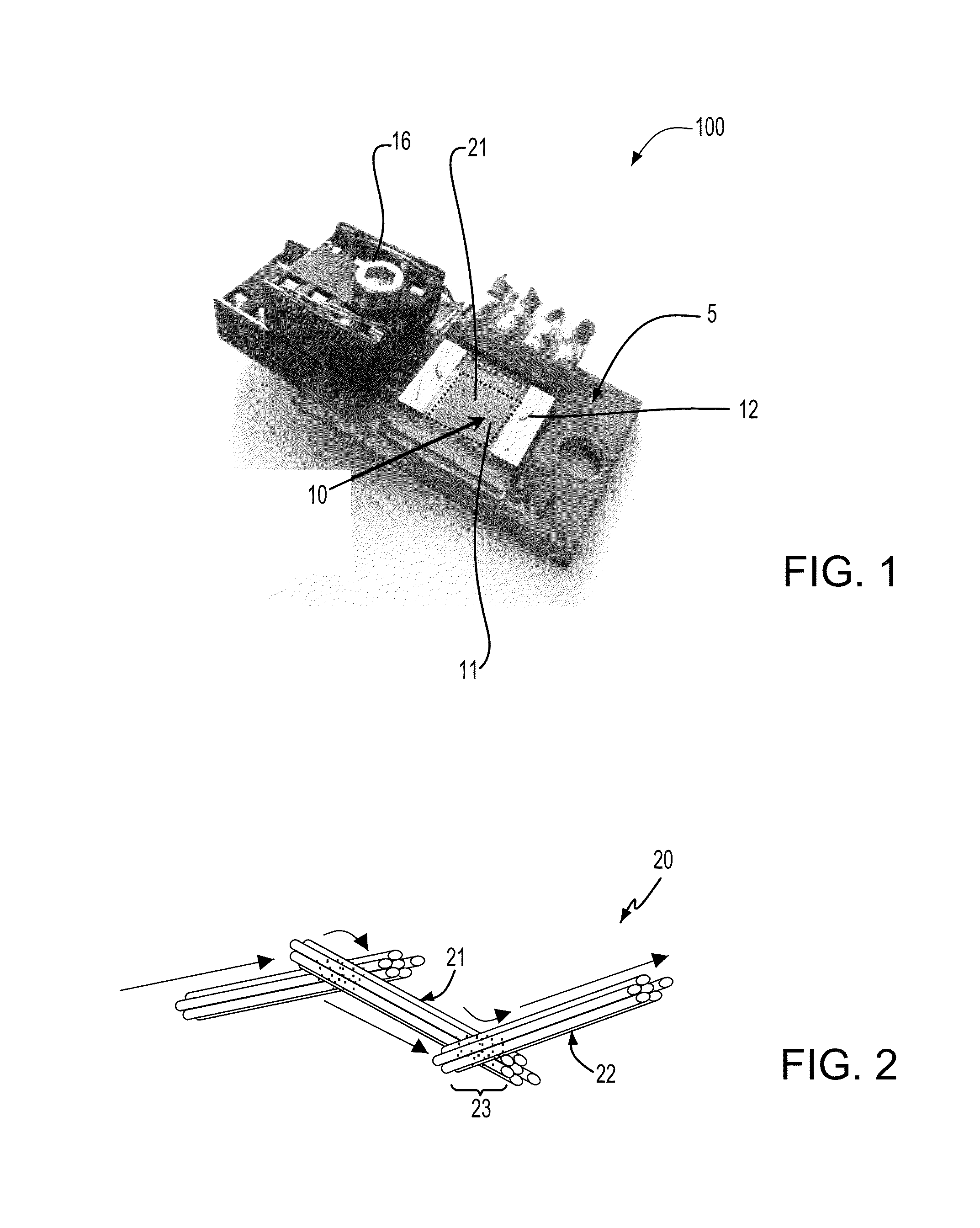
[0112]Single wall carbon nanotubes were synthesized by laser vaporization and purified by dilute HNO3 reflux / air oxidation procedure. A conjugated polymer poly(2-methoxy-5-(2′-ethylhexyloxy)-1,4-phenylenevinylene) (MEHPPV) was provided having a molecular weight of 51,000 and a polydispersity of 1.1 for the matrix in which the single wall nanotubes were fixed to provide a pad of electrically interconnected carbon nanotubes. The polymer matrix and the single wall carbon nanotubes were mixed to formulate a composite material that was spin cast onto a polymeric substrate to provide the sensor element 10 of a temperature sensor 100, as depicted in FIG. 1.

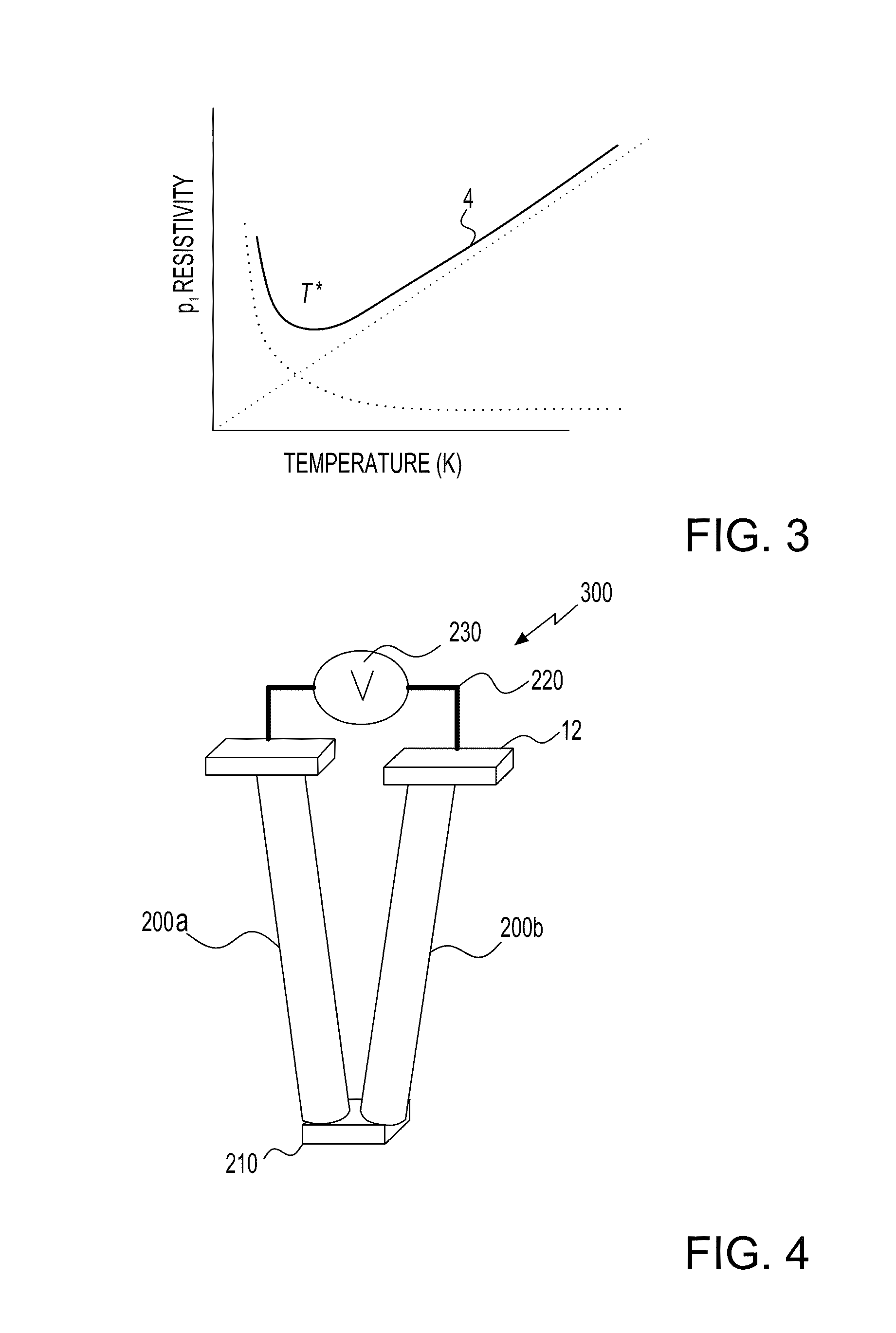
[0113]A 0.1 mA drive current was then applied to the sensor element including the electrically interconnected carbon nanotubes, while the sensor element was subjected to temperatures ranging from about 20° K to about 350° K. The resistance of the electrically interconnected carbon nanotubes was mea...

example 2

Linear Temperature Dependent Resistivity Independent of Pressure

[0117]FIGS. 10A and 10B are plots depicting the effect of static pressure on the temperature sensing abilities of the temperature sensor that provided the data illustrated in FIG. 9A. FIG. 10A depicts there is substantially no change in the linear response of the electrical properties of the sensing element to changes in temperature by the application of pressure to temperature sensor elements composed of single wall carbon nanotubes in which the number of junctions between each of the electrically interconnected nanostructures is fixed.

[0118]The temperature sensors were exposed to temperatures ranging from 20° C. to 50° C., and static pressures ranging from 10 g / cm2 to 4,000 g / cm2. The static pressure was provided by applying a load ranging from 18 g to approximately 8,445 g to an area of the sensor element on the order approximately 2.05 cm2. While under the applied load, the temperature sensor was subjected to increa...

example 3

Pressure Sensing

[0121]FIGS. 11A and 11B are plots of a change in voltage (delta voltage (V)) that is measured from the sensor element of a pressure sensor as a function of time, which illustrates the pressure sensing performance of a pressure sensor composed of vertically aligned carbon nanotube.

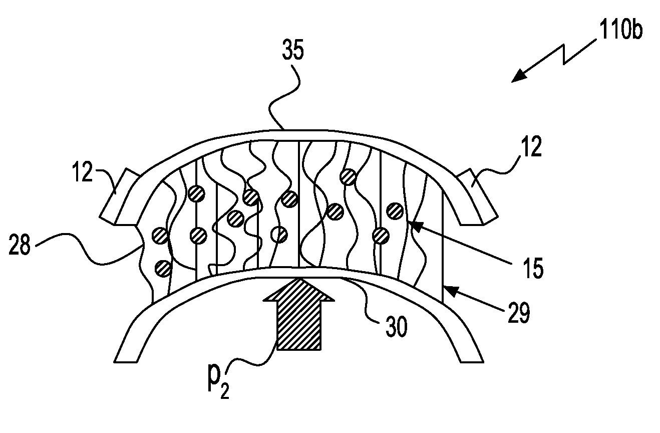
[0122]FIGS. 12A-12C illustrate the pressure sensor 110e that was used to generate the plots included in FIGS. 11A and 11B. The pressure sensor 110e includes a bundle of vertically aligned carbon nanotubes 15 that is in electrical communication with metal electrodes 12 at opposing ends of the bundle of vertically aligned carbon nanotubes 15. The electrodes 12 and connections thereto were arranged in a two point four wire configuration. FIGS. 12A-12C illustrate a progression in the pressure being applied to the pressure sensor 110e. FIG. 12A illustrates the bundle of vertically aligned carbon nanotubes 15 prior to the application of pressure. FIG. 12B illustrates the bundle of vertically align...


PUM

PropertyMeasurementUnit
thicknessaaaaaaaaaa
aspect ratioaaaaaaaaaa
shear modulusaaaaaaaaaa

Abstract

The present invention, in one embodiment, provides a method of measuring pressure or temperature using a sensor including a sensor element composed of a plurality of carbon nanotubes. In one example, the resistance of the plurality of carbon nanotubes is measured in response to the application of temperature or pressure. The changes in resistance are then recorded and correlated to temperature or pressure. In one embodiment, the present invention provides for independent measurement of pressure or temperature using the sensors disclosed herein.

Description

[0001]This invention was made with government support under contract no. DE-AC05-00OR22725 awarded by the U.S. Department of Energy. The government has certain rights in the invention.FIELD OF THE INVENTION[0002]The present invention generally relates to sensors composed of nanoscale structures, such as carbon nanotubes.BACKGROUND OF THE INVENTION[0003]Materials technology has had a profound impact on the evolution of human civilization. In the 21st century, people are developing smart materials and smart sensors. Typically, materials employed for temperature and pressure sensing applications, such as polymers, exhibit both responses simultaneously, making it difficult to determine whether a change in temperature, pressure or both has occurred. More specifically, because temperature and pressure sensors composed of polymeric sensing elements respond simultaneously to both pressure and temperature it is difficult to determine what external environment has been applied to the sensor.S...

Claims


Application Information

Patent Timeline
Patent Type & Authority Patents(United States)
IPC IPC(8): G01K7/14G01K7/16G01K7/21
CPCB82Y30/00G01K7/028G01K7/18G01L1/20G01L9/00G01L9/0001G01L9/0002G01L9/0005G01L19/00G01K7/00G01K7/021G01K2211/00Y10S977/956B82Y15/00Y10S977/742Y10S977/955
Inventor IVANOV, ILIA N.GEOHEGAN, DAVID BRUCE
Owner UT BATTELLE LLC
Why Eureka
Try Eureka