Semiconductor device and display apparatus
a technology of semiconductor devices and display devices, applied in the direction of semiconductor devices, thermoelectric device junction materials, electrical devices, etc., can solve the problems of delamination of the characteristics of organic thin film transistors, and achieve the effect of preventing delamination at the protective film interface and reducing the area of the interface in contact with other layers
- Summary
- Abstract
- Description
- Claims
- Application Information
AI Technical Summary
Benefits of technology
Problems solved by technology
Method used
Image
Examples
first embodiment
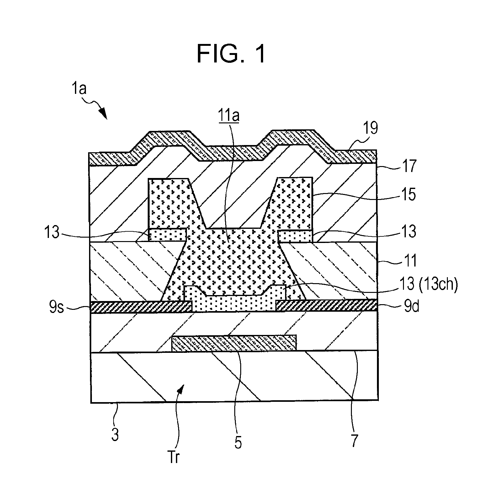
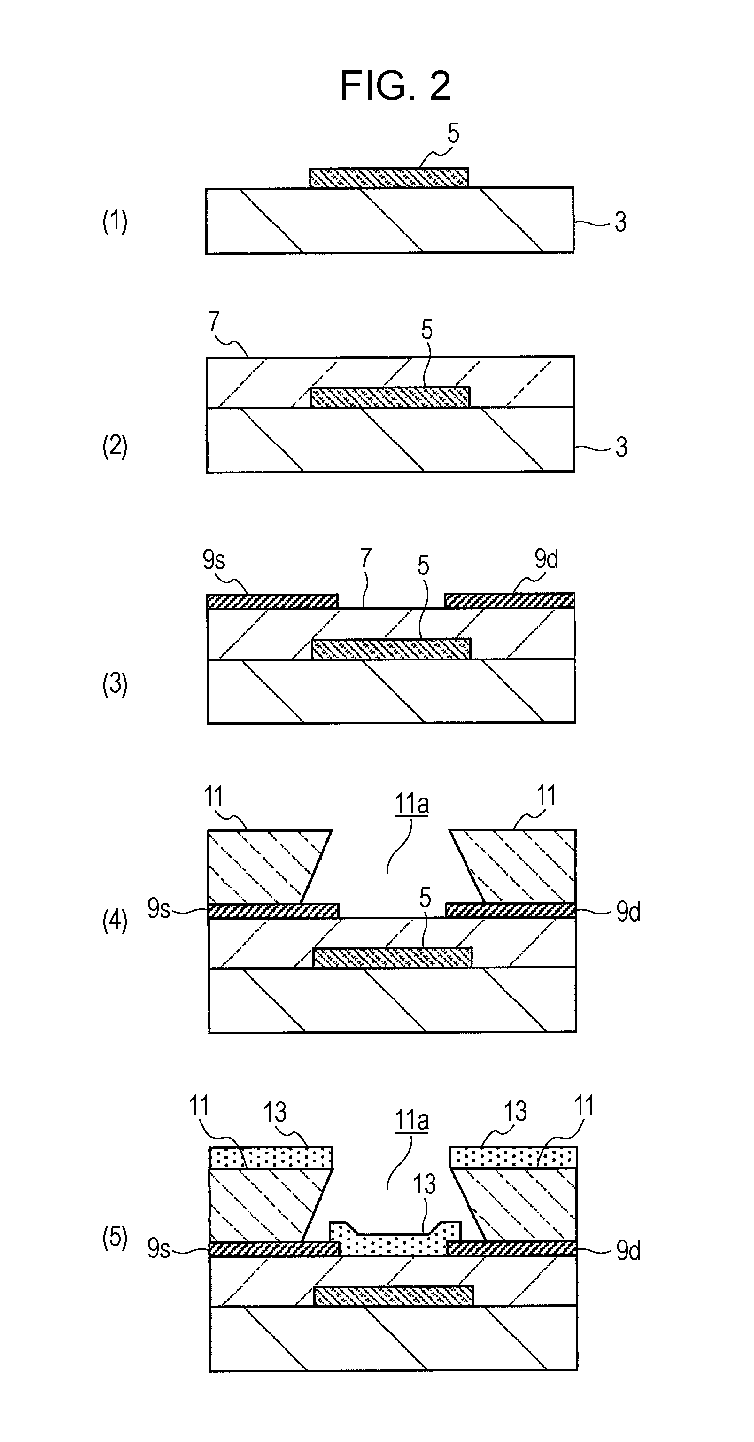
[0028]A semiconductor device 1a shown in FIG. 1 includes a bottom-gate-bottom-contact-type thin film transistor. In the semiconductor device 1a shown in this drawing, a gate electrode 5 composed of a conductive material is formed by patterning on a substrate 3. A gate-insulating film 7 is formed above the substrate 3 in such a state as to cover the gate electrode 5. On the gate-insulating film 7, a pair of a source electrode 9s and a drain electrode 9d composed of a conductive material are formed by patterning at both sides sandwiching the gate electrode 5.
[0029]A partition wall 11 composed of an insulating material is disposed above the substrate 3 provided with the source electrode 9s and the drain electrode 9d. An opening 11a is provided in the partition wall 11, the opening 11a exposing therethrough the surface of the gate-insulating film 7 between the source electrode 9S and the drain electrode 9d and ends of the source electrode 9S and the drain electrode 9d located on the sid...
second embodiment
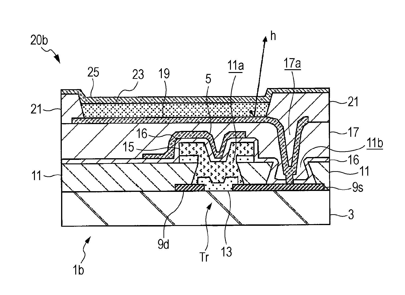
[0063]A semiconductor device 1b according to a second embodiment shown in FIG. 5 includes a top-gate-bottom-contact-type thin film transistor Tr′. The semiconductor device 1b shown in this drawing differs from the semiconductor device 1a according to the first embodiment described with reference to FIG. 1 in that the gate electrode 5 is disposed on the top of the insulating film 16 which covers the protective film 15, and the other configuration is the same as that of the first embodiment.
[0064]That is, the insulating film 16 is disposed in such a state as to cover the protective film 15, and the protective film 15 and the insulating film 16 constitute a gate-insulating film 7′. The gate electrode 5 composed of a conductive pattern is disposed on the gate-insulating film 7′.
[0065]Consequently, the second embodiment is the same as the first embodiment in that a pair of the source electrode 9s and the drain electrode 9d are formed by patterning on the top of the substrate 3, the parti...
third embodiment
[0085]A semiconductor device 1c according to a third embodiment shown in FIG. 8 includes a bottom-gate-bottom-contact-type thin film transistor Tr. The semiconductor device 1c shown in this drawing differs from the semiconductor device 1a according to the first embodiment described with reference to FIG. 1 in that the partition wall 11 is not disposed, and the other configuration is the same as that of the first embodiment.
[0086]That is, the semiconductor device 1c shown in FIG. 1 includes a bottom-gate-bottom-contact-type thin film transistor tr. In the semiconductor device 1c shown in this drawing, a gate electrode 5 composed of a conductive material is formed by patterning on a substrate 3. A gate-insulating film 7 is formed on the substrate 3 in such a state as to cover the gate electrode 5. On the gate-insulating film 7, a pair of a source electrode 9s and a drain electrode 9d composed of a conductive material are formed by patterning at both sides sandwiching the gate electrod...
PUM
 Abstract
Description
Claims
Application Information
 - R&D
- Intellectual Property
- Life Sciences
- Materials
- Tech Scout
- Unparalleled Data Quality
- Higher Quality Content
- 60% Fewer Hallucinations
Browse by: Latest US Patents, China's latest patents, Technical Efficacy Thesaurus, Application Domain, Technology Topic, Popular Technical Reports.
© 2025 PatSnap. All rights reserved.Legal|Privacy policy|Modern Slavery Act Transparency Statement|Sitemap|About US| Contact US: help@patsnap.com


