Blade for turbomachine receiving part, comprising an airfoil part including a mechanical fuse

a technology of mechanical fuse and turbomachine, which is applied in the direction of liquid fuel engines, vessel construction, marine propulsion, etc., can solve the problems of kinetic energy that increases with the mass, and the consequences of such a shock supply on the integrity of the fuselage, so as to reduce the risk of blade loss

Inactive Publication Date: 2013-11-05
AIRBUS OPERATIONS (SAS)
View PDF15 Cites 11 Cited by
  • Summary
  • Abstract
  • Description
  • Claims
  • Application Information

AI Technical Summary

Benefits of technology

[0005]With the blade according to the invention, the airfoil part will tend to break at its mechanical fuse if shocks on the airfoil part occur, for example caused by a bird during flight of the aircraft. Consequently, the part of the airfoil that could separate from the rest of the blade is smaller than what could occur in prior art. Therefore the mass of the debris formed from the separated portion is lower, and consequently can do less damage following an impact on the fuselage, due to its lower kinetic energy.
[0011]Consequently, if a failure occurs on one of the two portions of the blade root, such a crack, a corrosion development, a fatigue crack or delamination, it can only propagate within the portion of the root in which it originated. Consequently, the other root portion is advantageously not impacted by this failure, and it can therefore continue to hold the blade in contact with the hub, which significantly reduces risks of the blade being lost. In other words, this design prevents a crack, a corrosion development, a fatigue crack or delamination from propagating transversely throughout the blade root, each of the two root portions thus backing up the other portion, and therefore fulfilling a safety function in case of failure, also called a <<Fail Safe>> function.
[0016]Similarly, said part forming a bowl is preferably separated into two bowl portions one mounted on the other, each extending over the entire length of said bowl. Once again, if a failure such as a crack, a corrosion development, fatigue crack or delamination occurs on one of the two portions of bowl, it can only propagate within the portion of the bowl in which it originated. Consequently, the other bowl portion is advantageously not affected by this failure, and therefore can continue to participate in holding the blade onto the hub, which significantly reduces the risks of blade losses. In other words, the design prevents a crack, a corrosion development, a fatigue crack or delamination from propagating transversely entirely through the entire bowl, each of the two bowl portions thus backing up the other portion and therefore fulfilling a safety function in case of failure, also a <<Fail Safe>> function.

Problems solved by technology

This may be a major disadvantage considering that the debris could strike the fuselage of the aircraft, with a kinetic energy that increases with the mass.
The consequences on the integrity of the fuselage to which such a shock supplied may be disastrous.

Method used


Image

  • Blade for turbomachine receiving part, comprising an airfoil part including a mechanical fuse
  • Blade for turbomachine receiving part, comprising an airfoil part including a mechanical fuse
  • Blade for turbomachine receiving part, comprising an airfoil part including a mechanical fuse

Examples


Embodiment Construction

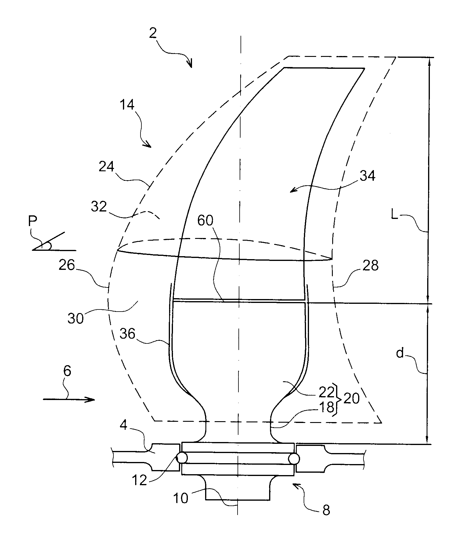
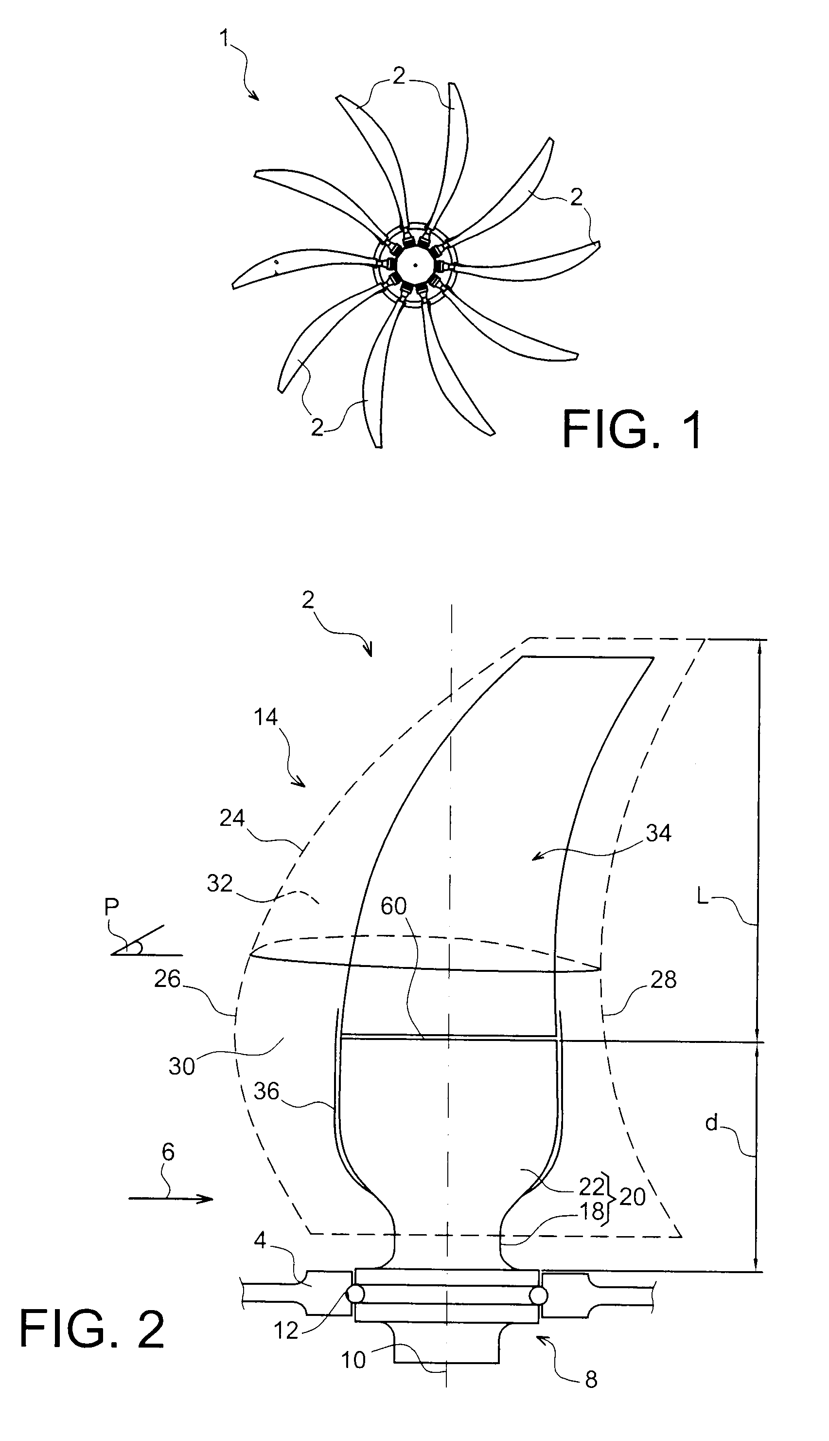
[0031]FIG. 1 shows a part of a receiving part of an open rotor type turbomachine, this receiving part corresponding to a propeller 1 equipped with a plurality of blades 2. For guidance, such a turbomachine comprises two counter rotating propellers, in a known manner, for example with the first fixed in rotation to a first free power turbine, and the second propeller fixed in rotation to a second free power turbine located on the downstream side of the first.

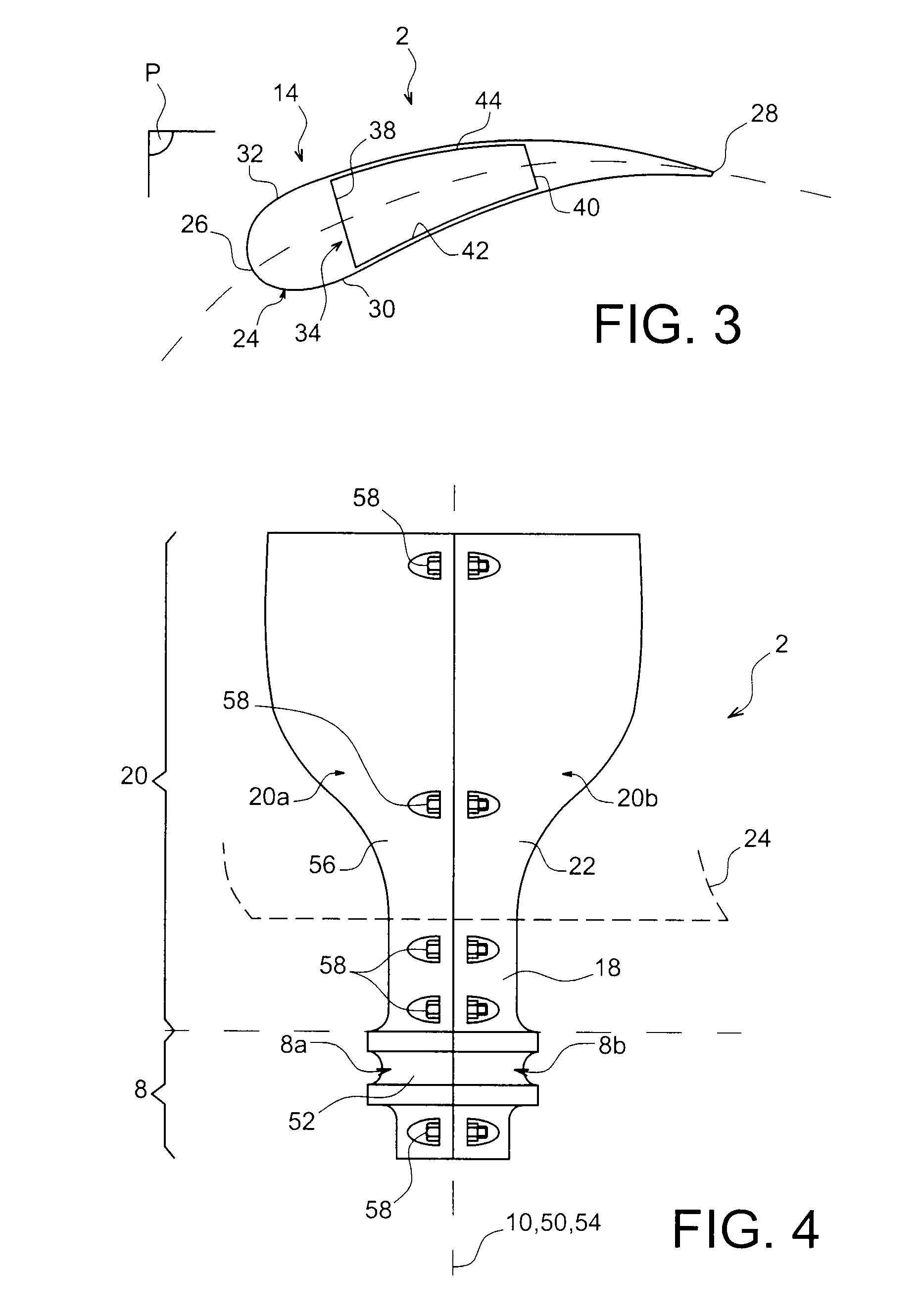
[0032]FIG. 2 shows one of the propeller blades 2 in the form of a first preferred embodiment of this invention. It is designed to be mounted free to rotate on a hub, this hub participating in delimiting the airstream 6. To achieve this, the blade 2 comprises a root 8 mounted rotating on the hub 4 about an axis 10, for example by means of a ball bearing system 12. In this way, it can continuously pivot during operation of the turbomachine to obtain the required incidence, by means of an appropriate variable pitch system (not shown...


PUM


Abstract

A blade for an aircraft turbomachine receiving part including a root, and an airfoil part prolonging this root. The airfoil part includes a mechanical fuse located at a distance from the bottom of the blade, along the length direction of the airfoil part, between 0.25 and 0.5 times the length of the airfoil part along this length direction.

Description

TECHNICAL DOMAIN[0001]This invention relates in general to blades fitting into a receiving part for an aircraft turbomachine. It is particularly applicable to turbojets, turboprops and turbomachines referred to as <<open rotor>>.STATE OF PRIOR ART[0002]Normally, such a blade has a root prolonged by an airfoil part that will be in the airstream of the turbomachine. The design is arranged to give acceptable stiffness, particularly through a hollow structural core forming a caisson provided within the airfoil part. Nevertheless, in case of shocks applied to the airfoil part, for example caused by a bird in flight or subsequent to the development of a fatigue crack, the part of the airfoil separated from the rest of the blade is usually a very large part of the airfoil or even all of it. The mass of the debris derived from the separated part is then large. This may be a major disadvantage considering that the debris could strike the fuselage of the aircraft, with a kinetic e...

Claims


Application Information

Patent Timeline
Patent Type & Authority Patents(United States)
IPC IPC(8): F01D5/14
CPCB64C11/24B64C11/26B64C11/48F01D5/147F02K3/072F04D27/0292F04D29/023F04D29/324B64D2027/026Y02T50/66Y02T50/672Y02T50/673F05D2230/51F05D2260/95Y02T50/60
Inventor LAFONT, LAUREN
Owner AIRBUS OPERATIONS (SAS)
Why Eureka
Try Eureka