Solid oxide fuel cell including electrode containing dense bonding portions and porous non-bonding portions

a solid oxide fuel cell and dense bonding technology, applied in the direction of cell components, final product manufacturing, sustainable manufacturing/processing, etc., can solve the problems of electrode and enhancement difficulties, and achieve the effect of reducing reaction resistance and increasing output of so

Active Publication Date: 2013-11-05
NGK INSULATORS LTD
View PDF29 Cites 0 Cited by
  • Summary
  • Abstract
  • Description
  • Claims
  • Application Information

AI Technical Summary

Benefits of technology

[0006]In the SOFC, a conductive current-collecting member (e.g., current-collecting mesh) for taking power based upon a potential difference to the outside is electrically connected and bonded to both of or each of the fuel electrode and the air electrode. From the viewpoint of enhancing the bonding strength of the bonding portion between the electrode and the current-collecting member, it is preferable that the porosity of the material forming the electrode is small in order to increase the bonding area or in order to enhance the strength of the electrode.
[0007]From above, it is difficult to attain both the enhancement in the diffusivity of the gas in the electrode and the enhancement in the bonding strength of the bonding portion between the electrode and the current-collecting member, if the porosity in the electrode of the SOFC is uniform. It has been desired to attain the enhancement in the diffusivity of the gas in the electrode, i.e., a high output, and the enhancement in the bonding strength of the bonding portion between the electrode and the current-collecting member, i.e., high reliability.
[0008]The present invention is accomplished for solving the foregoing problem, and aims to provide an SOFC that can attain both the enhancement in the diffusivity of the gas in the electrode, and the enhancement in the bonding strength of the bonding portion between the electrode and the current-collecting member.
[0012]With this structure, the porosity of the first portion on the electrode, i.e., the porosity of the “portion near the bonding portion with the current-collecting member” on the electrode, is less. As a result, the bonding strength of the bonding portion between the electrode and the current-collecting member is enhanced. On the other hand, the porosity of the second portion on the electrode, i.e., the porosity of the “remaining portion other than the first portion” on the electrode, is greater. Accordingly, when a gas externally supplied to the surface of the electrode is supplied to the “bonding portion between the electrode and the solid electrolyte film” through the pores in the electrode, it is easy to pass through the pores on the second portion having the large porosity. Consequently, the gas diffusivity in the electrode is enhanced. Thus, the enhancement in the gas diffusivity in the electrode and the enhancement in the bonding strength of the bonding portion between the electrode and the current-collecting member can simultaneously be attained.
[0014]With this structure, the gas enters the one electrode from the non-bonding portion on the second major surface of the one electrode. The gas entering the one electrode mainly moves inside of the second portion toward the first major surface. During this movement, the gas goes over the position corresponding to the bottom part of the first portion in the thickness direction of the one electrode, and then, can go around a region present between the bottom part of the first portion and the first major surface. Accordingly, the range where the gas can reach is increased on the bonding surface between the one electrode and the solid electrolyte film, compared to the structure in which the first portion continuously extends from the one or plural bonding portions up to the first major surface. Consequently, the reaction resistance of the SOFC can be reduced, whereby the output of the SOFC can be increased.

Problems solved by technology

From above, it is difficult to attain both the enhancement in the diffusivity of the gas in the electrode and the enhancement in the bonding strength of the bonding portion between the electrode and the current-collecting member, if the porosity in the electrode of the SOFC is uniform.

Method used


Image

  • Solid oxide fuel cell including electrode containing dense bonding portions and porous non-bonding portions
  • Solid oxide fuel cell including electrode containing dense bonding portions and porous non-bonding portions
  • Solid oxide fuel cell including electrode containing dense bonding portions and porous non-bonding portions

Examples


Embodiment Construction

(Structure)

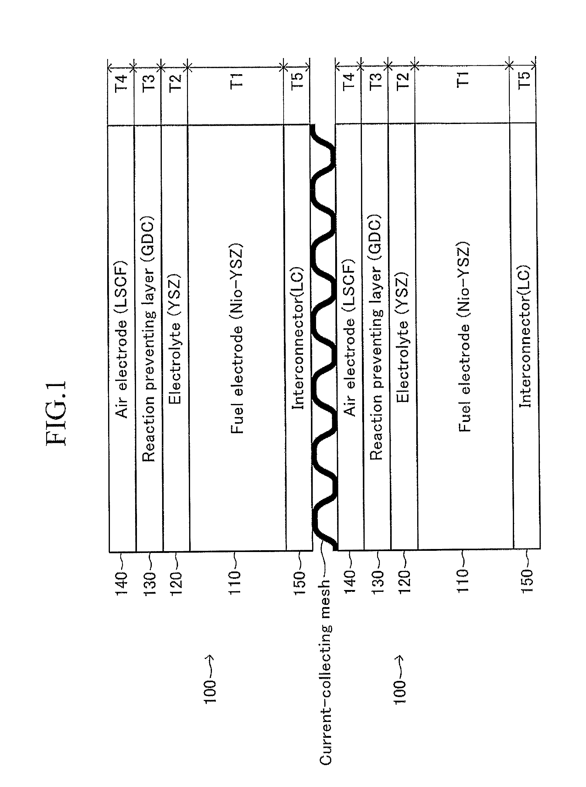
[0018]FIG. 1 illustrates one example of an SOFC according to an embodiment of the present invention. In FIG. 1, two SOFC cells 100 and 100 are electrically connected in series through a current-collecting mesh. Each SOFC cell 100 will firstly be described below.

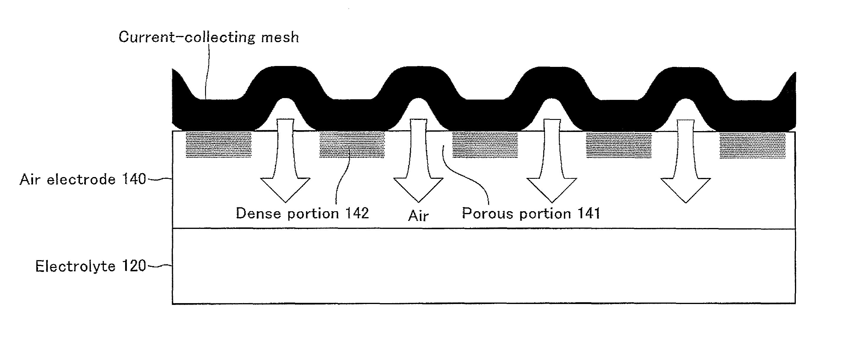
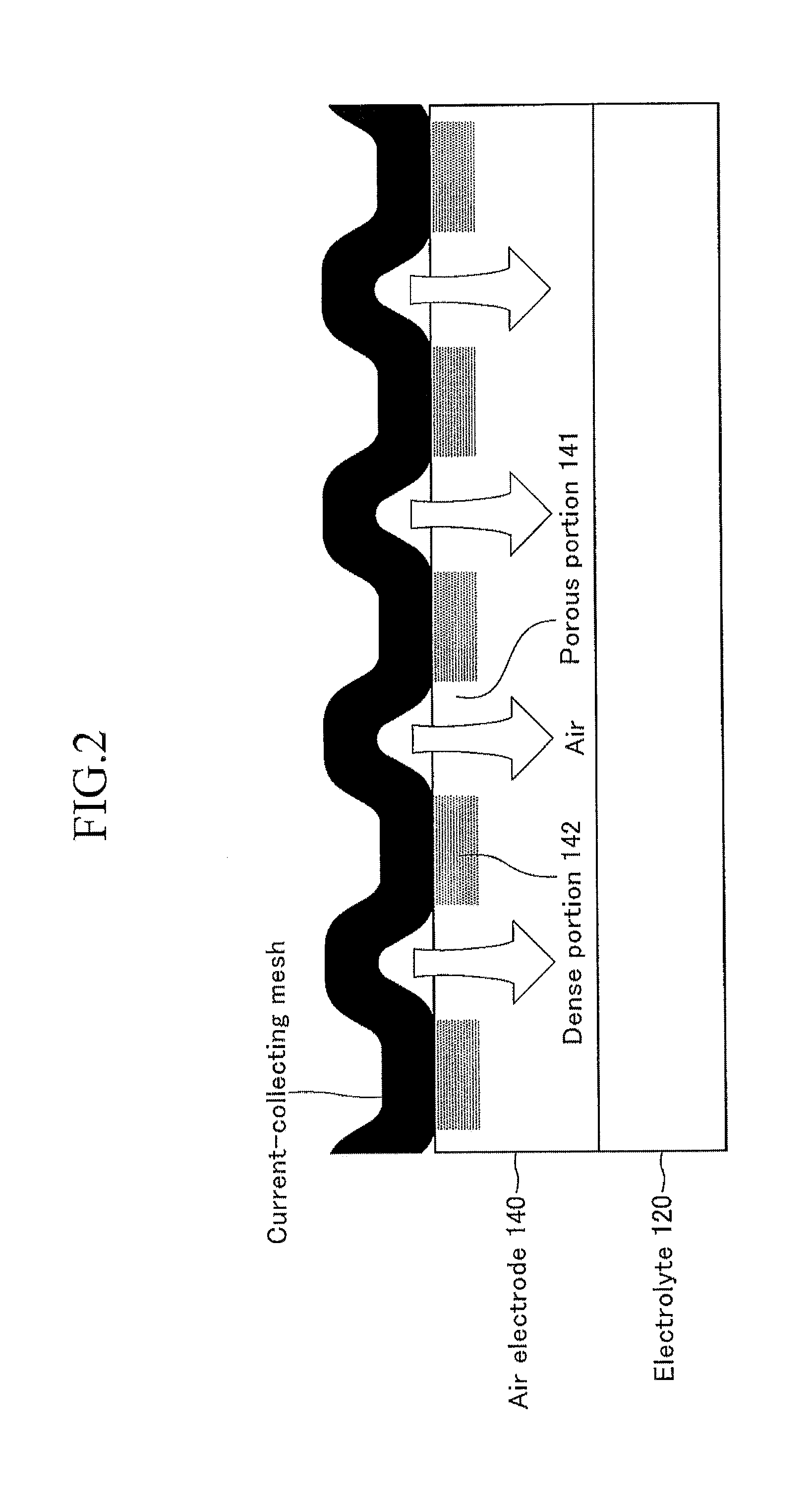
[0019]The SOFC cell 100 is a stacked body including a fuel electrode 110, a solid electrolyte film 120 stacked on the fuel electrode 110, a reaction preventing layer 130 stacked on the solid electrolyte film 120, an air electrode 140 stacked on the reaction preventing layer 130, and an interconnector 150 stacked below the fuel electrode 110. The shape of the cell 100 viewed from the top is, for example, a square having a side of 1 to 30 cm, a rectangle having a long side of 5 to 30 cm and a short side of 3 to 15 cm, or a circle having a diameter of 1 to 30 cm. The thickness of the cell 100 is 0.1 to 3 mm.

[0020]The fuel electrode 110 (anode electrode) is, for example, a sheet-type porous sintered body composed of ni...


PUM

PropertyMeasurementUnit
porosityaaaaaaaaaa
porosityaaaaaaaaaa
porosityaaaaaaaaaa

Abstract

A solid oxide fuel cell having a fuel electrode, a solid electrolyte film, an air electrode, and a conductive current-collecting mesh bonded to an upper surface, opposite to a lower bonding surface with the solid electrolyte film, of the air electrode. Plural bonding portions that are bonded to the current-collecting mesh and plural non-bonding portions that are not bonded to the current-collecting mesh are present on the upper surface of the air electrode. In the air electrode, regions having a porosity smaller than a porosity of the other region are respectively formed on the position in the middle of the thickness of the air electrode from each bonding portion. The average of the porosity of the dense portion is 20% or more and less than 35%, while the average of the porosity of the porous portion is 35% or more and less than 55%.

Description

BACKGROUND OF THE INVENTION[0001]1. Field of the Invention[0002]The present invention relates to a solid oxide fuel cell (SOFC).[0003]2. Description of the Related Art[0004]An SOFC includes a fuel electrode that is in contact with a fuel gas to react the fuel gas; a solid electrolyte film bonded to the fuel electrode; and an air electrode that reacts a gas containing oxygen, and that is bonded to the solid electrolyte film so as to sandwich the solid electrolyte film between the fuel electrode and the air electrode (see, for example, Japanese Unexamined Patent Application No. 2005-339904). A fuel gas (hydrogen gas, etc.) is supplied to the fuel electrode of the SOFC and a gas (air, etc.) containing oxygen is supplied to the air electrode of the SOFC, whereby a chemical reaction represented by Formulas (1) and (2) described below is generated. Thus, a potential difference is produced between the fuel electrode and the air electrode.(½).O2+2e−→O2− (at air electrode)  (1)H2+O2−→H2O+2e−...

Claims


Application Information

Patent Timeline
Patent Type & Authority Patents(United States)
IPC IPC(8): H01M4/02H01M4/64H01M4/36H01M8/10H01M8/22
CPCH01M4/861H01M8/0254H01M8/1213H01M8/1246Y02E60/521Y02E60/525Y02E60/50Y02P70/50
Inventor KOBAYASHI, AYANOOHMORI, MAKOTO
Owner NGK INSULATORS LTD
Why Eureka
Try Eureka