
Ceramic burner for ceramic metal halide lamp

a ceramic metal halide lamp and ceramic burner technology, which is applied in the manufacture of cold cathode, electrode system, electric discharge tube/lamp, etc., can solve the problems of no longer being able to seal the known container via local heating, cracks in the ceramic material of the container, etc., and achieve less sealing material, less time, and less tolerances on the projecting end of the tub

Inactive Publication Date: 2013-11-05
KONINK PHILIPS ELECTRONICS NV +1
View PDF12 Cites 5 Cited by
  • Summary
  • Abstract
  • Description
  • Claims
  • Application Information

AI Technical Summary

Benefits of technology

This design enables miniaturization of the discharge vessel while maintaining a gastight seal without overheating, reducing processing time, and ensuring color stability by preventing condensation of filling compounds.

Problems solved by technology

The laser irradiation locally increases the temperature of the T-shaped plug and the container to the melting temperature of the ceramic material, which is around 2100° C. This local increase of the temperature creates a considerable local temperature gradient which may result in cracks in the ceramic material of the container.
The inventors have realized that when miniaturizing the discharge vessel, the sealing of the known container via local heating of the container is no longer feasible without increasing the temperature of the entire container.

Method used


Image

  • Ceramic burner for ceramic metal halide lamp
  • Ceramic burner for ceramic metal halide lamp
  • Ceramic burner for ceramic metal halide lamp

Examples


Embodiment Construction

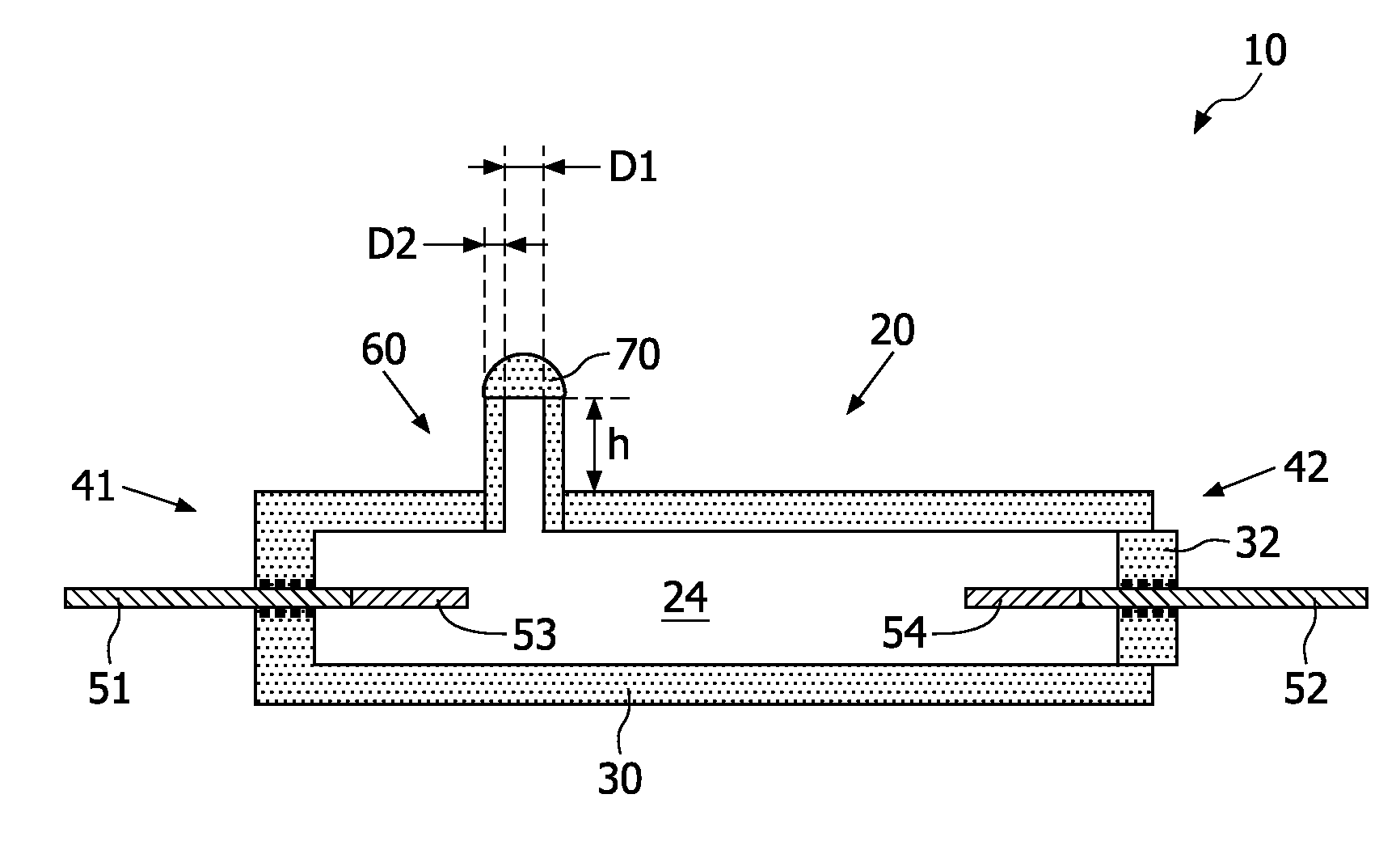
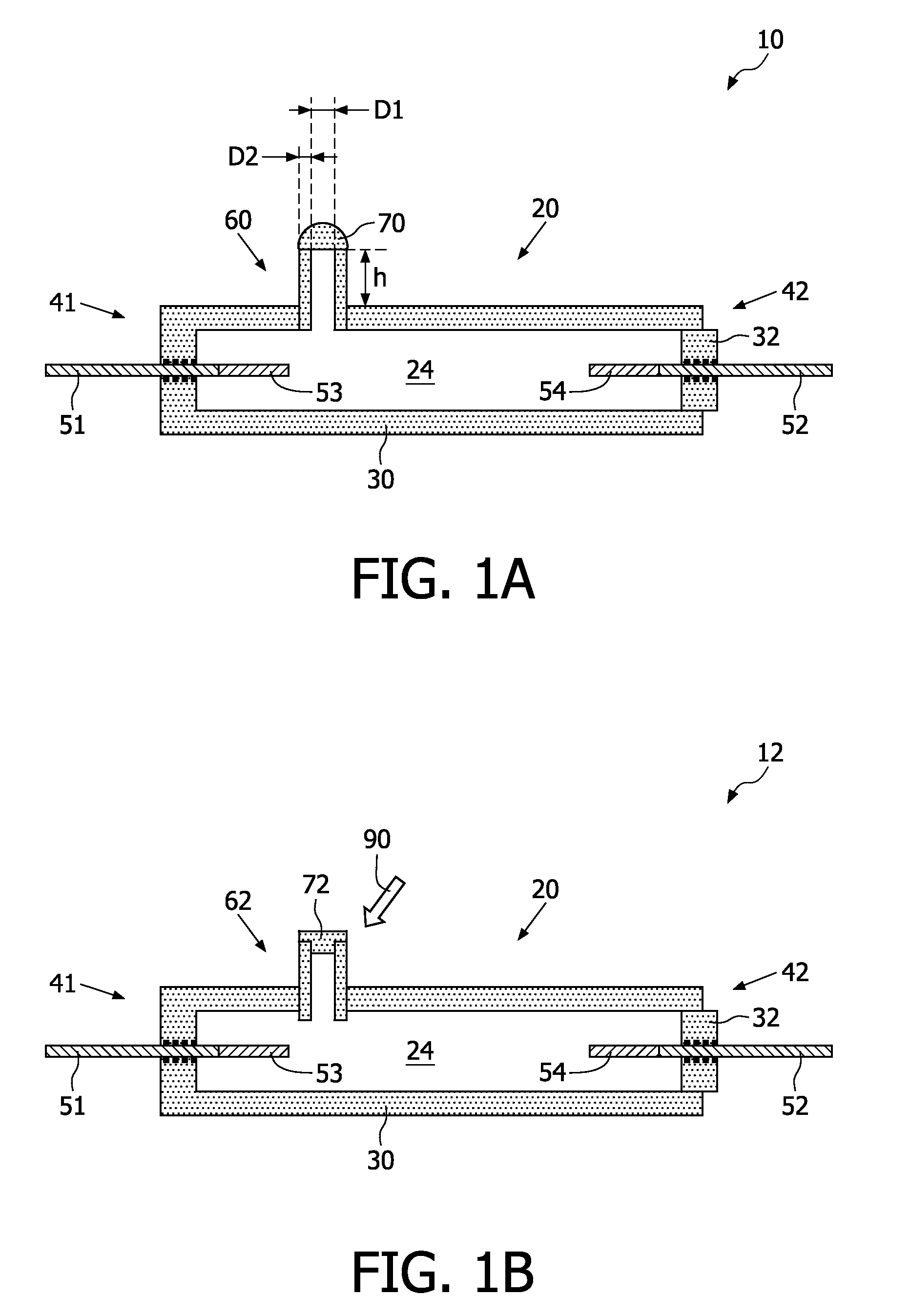
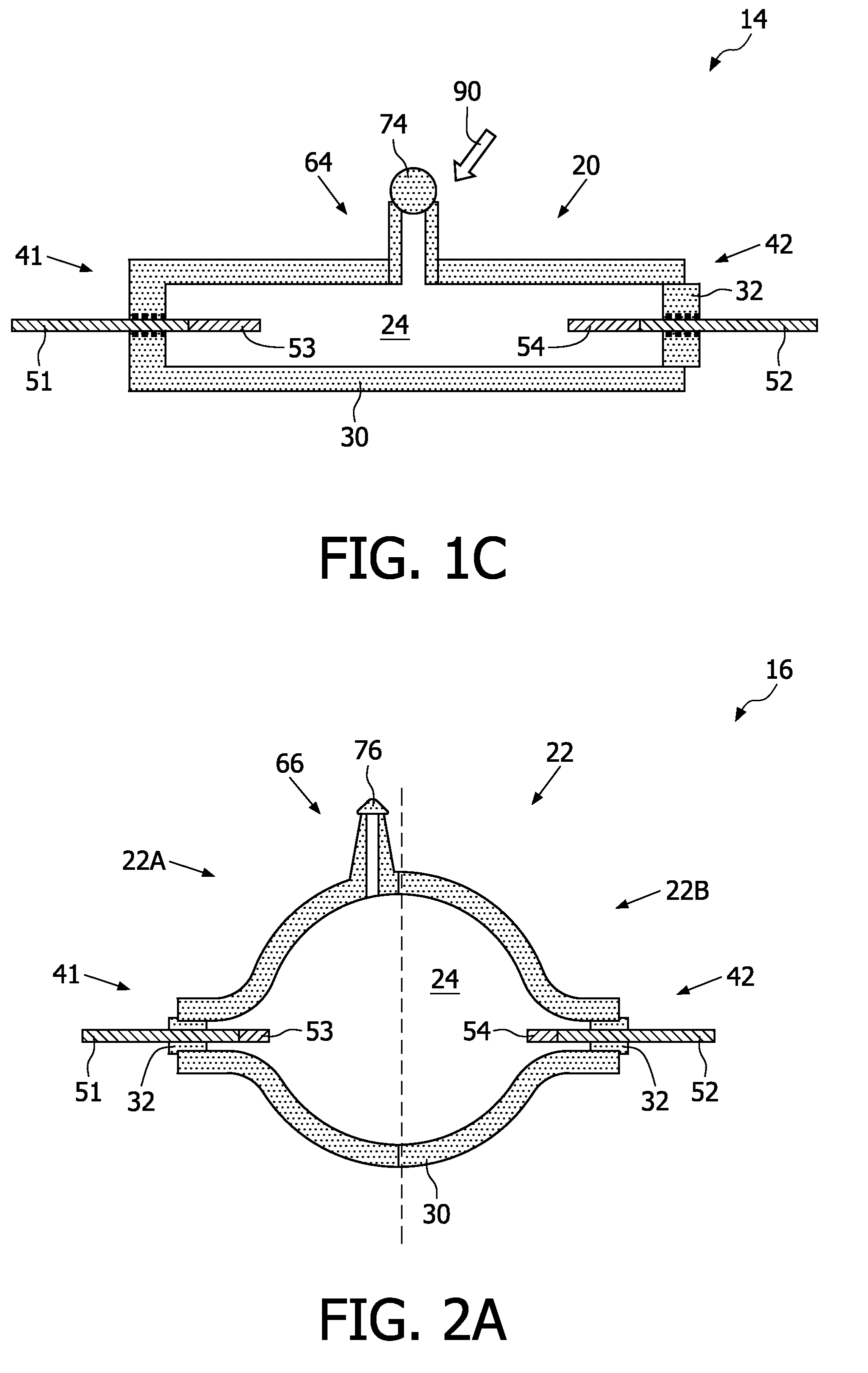
[0031]FIGS. 1A, 1B and 1C are cross-sectional views of embodiments of a ceramic burner 10, 12, 14 according to the invention having a cylindrical discharge vessel 20. The ceramic burner 10, 12, 14 comprises a discharge vessel 20 enclosing a discharge space 24. The discharge vessel 20 is substantially formed from a ceramic material, such as aluminum oxide (Al2O3). The discharge vessel 20 comprises a first and a second end portion 41, 42 where the current supply conductors 51, 52 are passed through the discharge vessel 20. The current supply conductors 51, 52 are preferably formed by rods 51, 52 directly sintered into the ceramic material of the discharge vessel 20. Generally, an electrode 53, 54 is connected to the current supply conductors 51, 52 at a side of the current supply conductors 51, 52 facing the discharge space 24. The electrode 53, 54 is often made from tungsten. The current supply conductors 51, 52 are connected to the electrodes 53, 54 for supplying power to the electr...


PUM

PropertyMeasurementUnit
thicknessaaaaaaaaaa
thicknessaaaaaaaaaa
inner diameteraaaaaaaaaa

Abstract

A ceramic burner, a ceramic metal halide lamp, and a method of sealing the ceramic burner is provided. The ceramic burner comprises a discharge vessel enclosing a discharge space that is provided with an ionizable filling comprising one or more halides. The discharge vessel comprises a ceramic wall arranged between a first and a second end portion. The first and the second end portion are arranged such that current supply conductors are passed through the end portions to respective electrodes arranged in the discharge space for maintaining a discharge. The ceramic wall of the discharge vessel comprises a tube for introducing the ionizable filling into the discharge vessel during manufacture of the ceramic burner. The tube projects from the ceramic wall and is provided with a gastight seal. The effect of using the tube is that it enables the gastight seal to be arranged away from the ceramic wall of the discharge vessel at a projecting end of the tube.

Description

FIELD OF THE INVENTION[0001]The invention relates to a ceramic burner for a ceramic metal halide lamp.[0002]The invention also relates to a ceramic metal halide lamp and to a method of sealing the ceramic burner.BACKGROUND OF THE INVENTION[0003]Ceramic metal halide lamps contain fillings which comprise besides a starter gas also metal halide salt mixtures such as NaCe iodide, NaTl iodide, NaSc iodide, NaTlDy iodide, or combinations of these salts. These metal halide salt mixtures are applied to obtain, inter alia, a high luminous efficacy, a specific color-corrected temperature, and a specific color rendering index.[0004]Generally, such ceramic metal halide lamps comprise a discharge vessel enclosing a discharge space comprising the filling of the metal halide salt mixtures. The discharge space further comprises electrodes between which a discharge is maintained. Typically, the electrodes pierce through the discharge vessel. To fill the ceramic metal halide lamp with the metal halid...

Claims


Application Information

Patent Timeline
Patent Type & Authority Patents(United States)
IPC IPC(8): H01J5/48H01J17/16H01J61/30H01K3/22
CPCH01J9/395H01J9/40H01J61/30H01J61/827
Inventor RAAS, MARINUS CORNELISHAKKENS, FRANCISCUS JOHANNES GERARDUSDIJKEN, DURANDUS KORNELIUSDE NIJS, ADRIANUS GERARDUS MARIADORRESTEIN, ALEXANDER JOHANNES ADRIANUS CORNELIAHENDRICX, JOSEPHUS CHRISTIAAN MARIAVRUGT, PETER JOZEF
Owner KONINK PHILIPS ELECTRONICS NV
Learn More