Power converter with low ripple output

a power converter and low ripple technology, applied in the direction of dc-ac conversion without reversal, dc source parallel operation, dc network circuit arrangement, etc., can solve the problems of discontinuous rectified voltage, large, heavy, and preponderance of switching power supplies, and achieve low cost, low cost, and low cost

Active Publication Date: 2013-11-05
THX
View PDF15 Cites 12 Cited by
  • Summary
  • Abstract
  • Description
  • Claims
  • Application Information

AI Technical Summary

Benefits of technology

[0021]Embodiments as described herein may result in one or more advantages, including being smaller, lighter, thinner and / or less expensive than a conventional power supply, with fewer large components, while retaining high efficiency. The power supply can be designed so as to produce minimal or insignificant EMI. Because the power supply can be simpler to design and manufacture, it can be brought to market more quickly, thus resulting in a faster product design cycle.

Problems solved by technology

The demand for ever smaller equipment has led to a preponderance of switching power supplies.
Conventional linear power supplies, used for instance in home audio amplifiers, use a large, heavy, expensive transformer to convert a low frequency, high-voltage AC line supply to a lower voltage suitable for the amplifier or other application.
However, the rectified voltage is discontinuous and so large storage capacitors are needed in order to provide a smooth voltage for the amplifier.
Even so, the DC supply still has an appreciable irregularity (the ripple voltage) superimposed upon the DC which can manifest as an audible hum and buzz at the amplifier output unless considerable care is taken with the amplifier design and layout.
While the design of such a power supply is relatively simple and the EMI emissions relatively low, the transformer is large, heavy and very expensive.
The storage capacitors are also large and expensive.
Thus the overall bulk of this power supply approach precludes its use on lightweight, low profile designs.
One penalty to be paid in this approach is that, in order to retain efficiency, the chopping of the DC produces high frequency AC with a discontinuous, square waveshape.
Such a waveshape generates high levels of very high frequencies which radiate to cause radio frequency interference (EMI).
The switching frequency components also need to be removed or isolated from the input and output lines, requiring extra magnetic components that add to the cost and bulk of the supply.
However, the complexities inherent in the design of a switching power supply can add considerably to the design and certification costs and result in a time to market of many months.
In sum, linear power supplies tend to be larger in size and profile, relatively costly, and heavy.
However, switching power supplies can be less efficient than linear power supplies, and produce significantly more EMI which requires careful filtering and screening.
Switching power supplies are also more complex, needing control circuitry and power switching devices.
They take longer to design and are generally more expensive than linear power supplies.
The trend is towards ever smaller power supplies, requiring higher frequency operation and hence more potential issues relating to EMI.
While three-phase power supply systems have some benefits, they are also subject to certain drawbacks or limitations.

Method used


Image

  • Power converter with low ripple output
  • Power converter with low ripple output
  • Power converter with low ripple output

Examples


Embodiment Construction

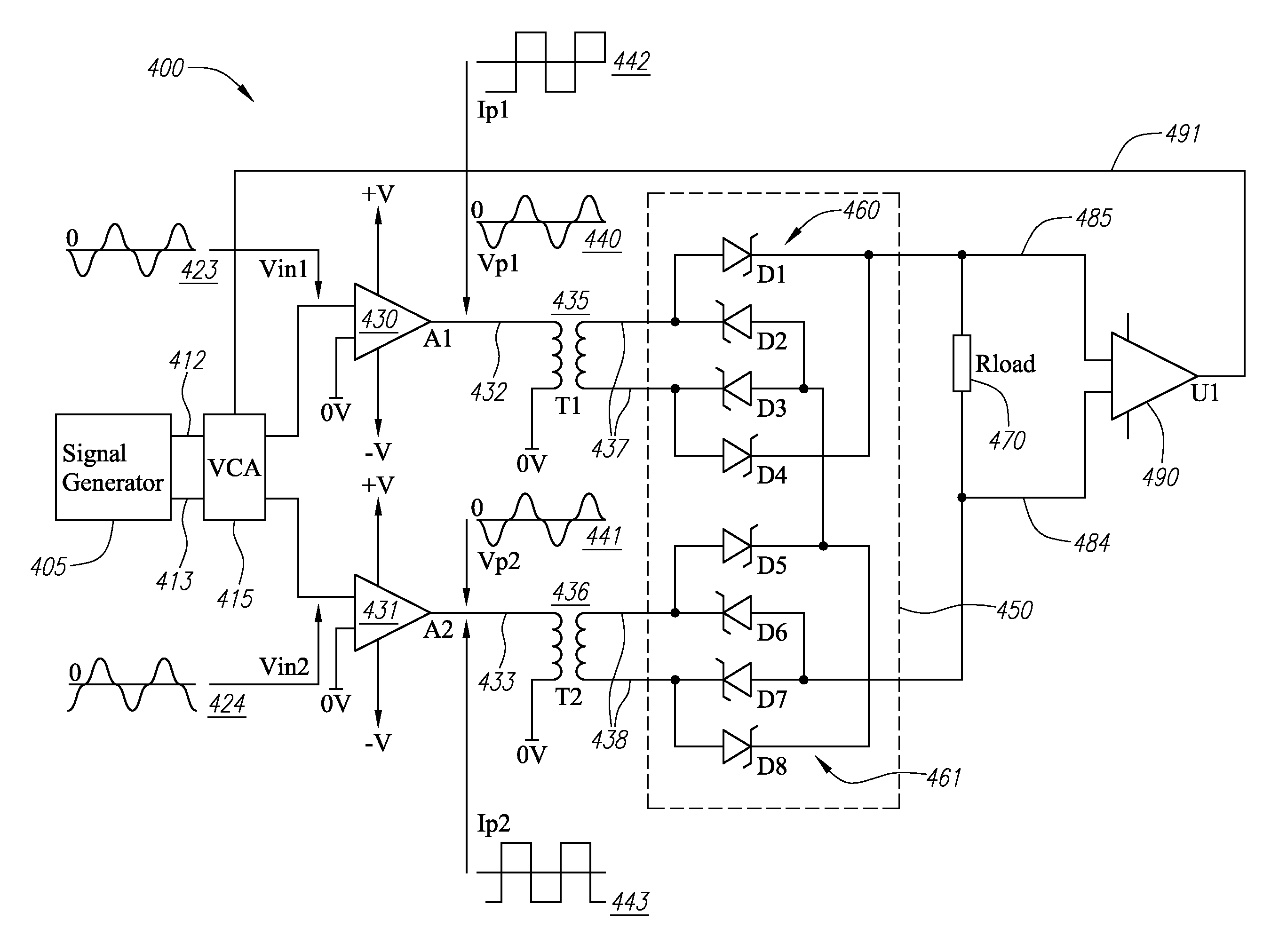
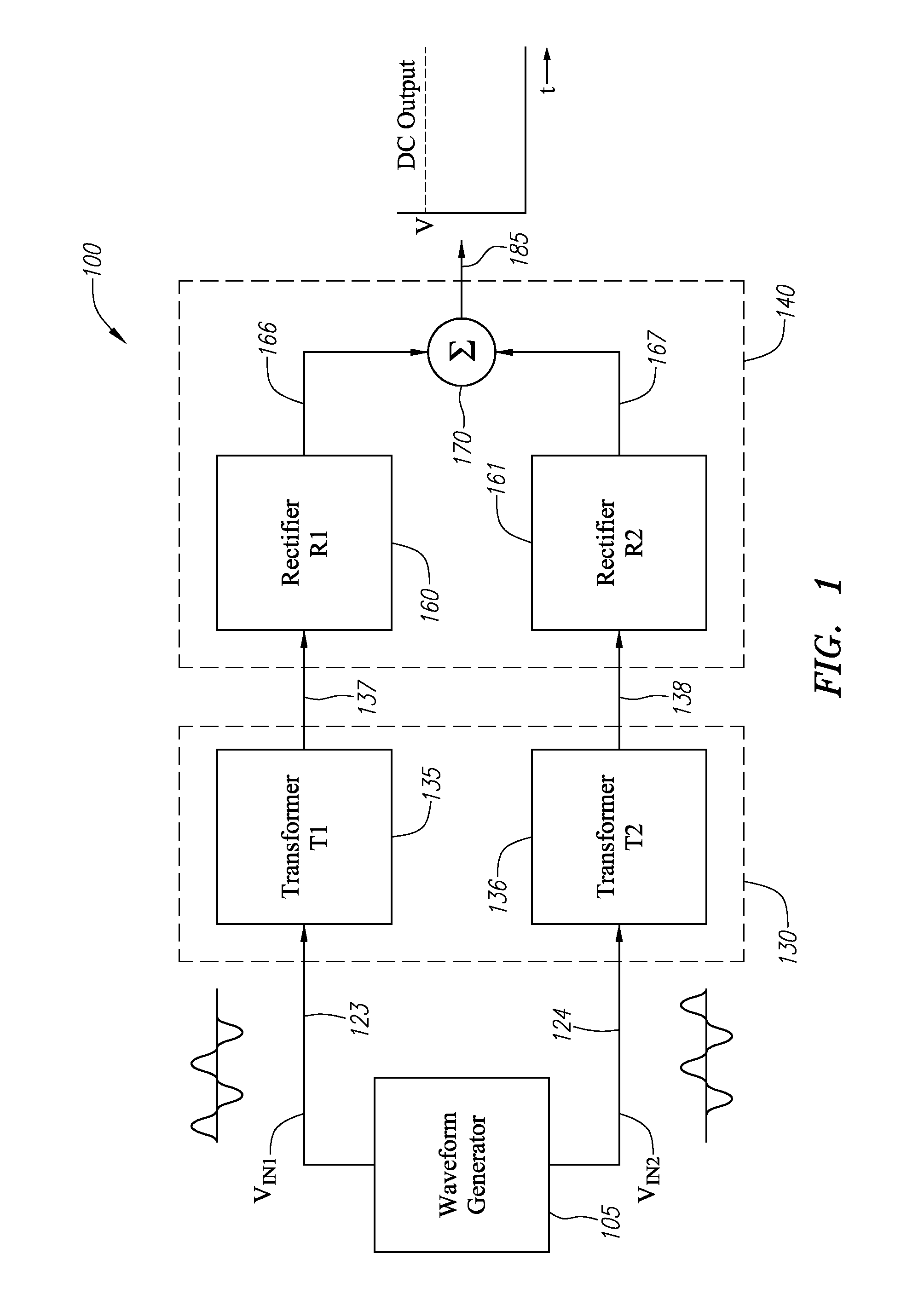
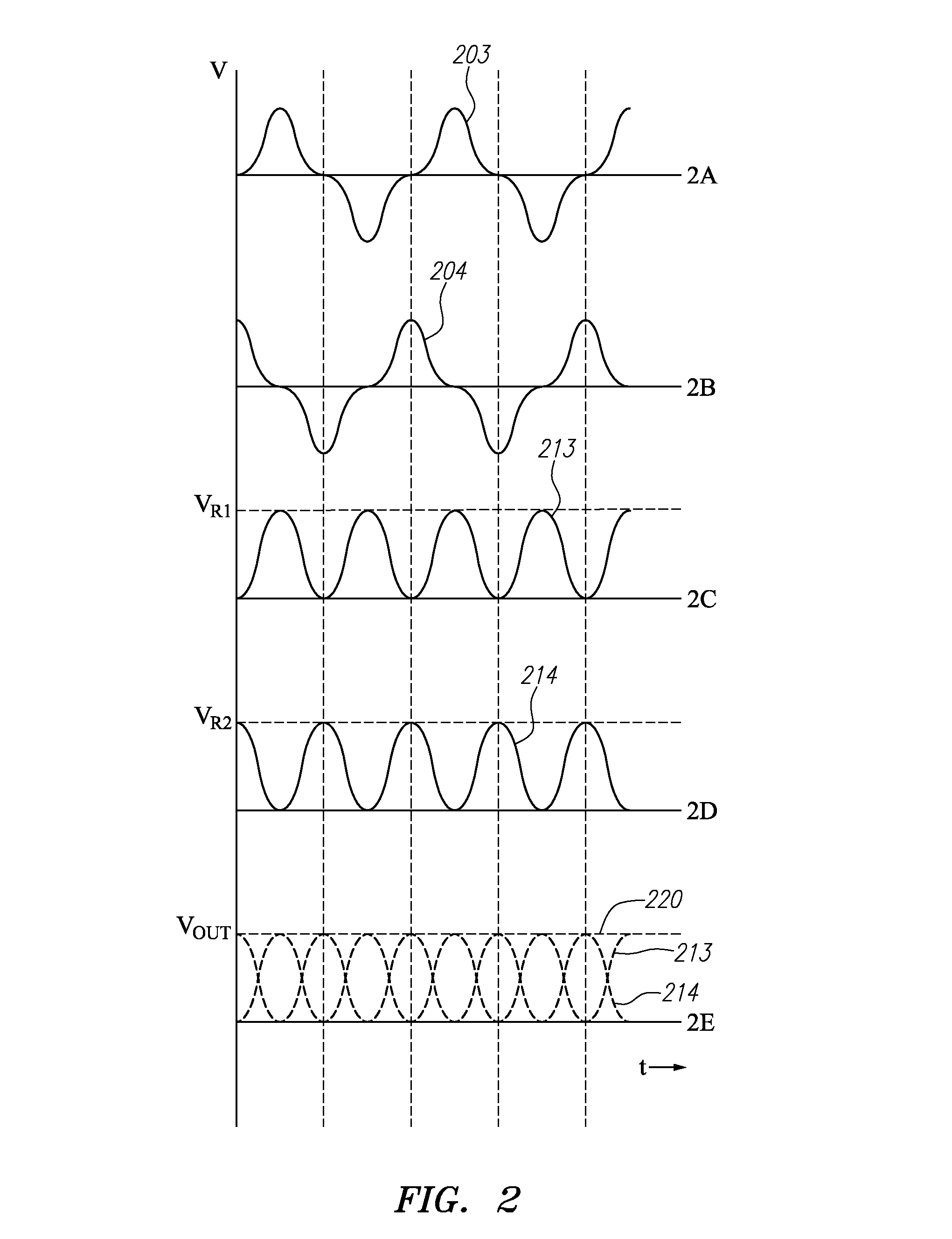
[0041]According to one or more embodiments, a power supply is provided having one or more input waveforms are shaped or otherwise selected prior to being provided to an isolating transformer. The nature of the input waveforms is shaped, selected or otherwise generated so that the transformed waveform requires minimal rectification and / or smoothing for generation of a DC output waveform.

[0042]FIG. 8 is a conceptual block diagram of a power supply 800 as disclosed herein. In FIG. 8, a signal source (waveform) generator 805 generates a pair of complementary waveform signals 823, 824. The complementary waveform signals 823, 824 are selected so as to provide a constant DC output level after being coupled through a level conversion stage 830 to an output (rectification) stage 840 whereupon the level-converted signals are rectified and combined, while minimizing storage / smoothing capacitor requirements in the output stage 840. The complementary waveform signals 823, 824 are preferably of a...


PUM


Abstract

A power supply includes two or more input waveforms being shaped or selected so that after being separately level-shifted and rectified, their additive combination results in a DC output waveform with substantially no ripple. The power supply may comprise a waveform generator, a level conversion stage for step up or down conversion, a rectification stage, and a combiner. The waveform generator may generate complementary waveforms, preferably identical but phase offset from each other, such that after the complementary waveforms are level-converted, rectified and additively combined their sum will be constant, thus requiring no or minimal smoothing for generation of a DC output waveform. The level conversion may be carried out using transformers or switched capacitor circuits. Feedback from the DC output waveform may be used to adjust the characteristics of the input waveforms.

Description

RELATED APPLICATION INFORMATION[0001]This application claims the benefit of U.S. Provisional Application Ser. No. 61 / 229,217, filed on Jul. 28, 2009, hereby incorporated by reference as if set forth fully herein.BACKGROUND OF THE INVENTION[0002]1. Field of the Invention[0003]The field of the invention generally relates to power supplies and, more specifically, to a versatile DC output power supply.[0004]2. Background of the Related Art[0005]There are two main classes of power supply or converter: (1) AC to DC, and (2) DC to DC. An AC to DC power supply generally converts AC line voltage as its input to a DC output voltage and is found, for example, in applications such as home audio amplifiers. It can generally be implemented as either a linear or switching power supply. A DC to DC power supply converts from one existing DC voltage to another, for example from a battery, to another higher or lower voltage level. It is typically implemented with a switching power supply. For general ...

Claims


Application Information

Patent Timeline
Patent Type & Authority Patents(United States)
IPC IPC(8): H02M7/04
CPCH02M1/14H02M3/07H02M7/10H02M3/22H02M3/155
Inventor JONES, OWENFINCHAM, LAWRENCE R.
Owner THX
Why Eureka
Try Eureka