Power transmission belt method for production thereof

a transmission belt and transmission belt technology, applied in the field of transmission belts, can solve the problems of increasing the cost of assembling the elements to the stacked ring, the process of applying residual compressive stress to the ring materials typically increases the cost, and the endless sheet metals of the inner layers (especially the innermost layer) tend to degrade, so as to suppress the increase in compressive stress, increase the strength of the ring materials of the first to mth layers, and reduce the cost

Inactive Publication Date: 2013-11-12
AISIN AW CO LTD
View PDF22 Cites 2 Cited by
  • Summary
  • Abstract
  • Description
  • Claims
  • Application Information

AI Technical Summary

Benefits of technology

[0006]Thus, it is a primary object of the present invention to reduce a stress that is generated in ring materials when a transmission belt is used, while satisfactorily maintaining assembling capability of elements to a stacked ring and suppressing an increase in cost, in the transmission belt including the stacked ring formed by stacking the plurality of elastically deformable ring materials together.
[0017]When forming the stacked ring by this method, each of the ring materials of the first to mth layers is press-fit into the ring material located on the outer circumference side thereof (that is, located immediately outside thereof). Thus, a compressive stress is further applied to the ring materials of the first to mth layers, whereby the strength of the ring materials of the first to mth layers can further be increased. The surfaces of the ring materials of the first to mth layers are subjected to the surface treatment for applying the residual compressive stress so that the residual compressive stress in the ring materials of the first to mth layers is higher than that in the ring material of the (m+1)th layer. This can suppress an increase in cost associated with the surface treatment, as compared to the case where the surface treatment for applying the residual compressive stress is performed on the ring materials of all the layers. Moreover, performing the surface treatment on the surfaces of the ring materials of the first to mth layers can suppress an increase in compressive stress that should be applied to the ring materials of the first to mth layers by press-fitting each of the ring materials of the first to mth layers into the ring material on the outer layer side thereof, namely an increase in difference between the outer circumferential length of each of the ring materials on the inner layer side (the first to mth layers) and the inner circumferential length of the ring material on the outer layer side thereof (the second to (m+1)th layers). Thus, adhesion can be satisfactorily ensured between adjacent ones of the ring materials located on the inner side of the (m+1)th layer. As a result, according to this method, an increase in cost is suppressed by reducing the number of ring materials to be subjected to the shot peening, and assembling capability of the elements to the stacked ring is satisfactorily maintained by satisfactorily ensuring adhesion between the ring materials. At the same time, the stress that is generated in the ring materials when the transmission belt is used can be reduced.

Problems solved by technology

However, even in the transmission belts having such a structure, the endless sheet metals of the inner layers (especially the innermost layer) tend to degrade after a long period of use.
JP-A-H10-169719, which can make assembling of the elements to the stacked ring troublesome.
However, the process of applying the residual compressive stress to the ring materials typically increases the cost, as compared to the process of making the outer circumferential length of the inner ring equal to or longer than the inner circumferential length of the outer ring as measured before fitting adjacent ones of the rings on each other.

Method used


Image

  • Power transmission belt method for production thereof
  • Power transmission belt method for production thereof
  • Power transmission belt method for production thereof

Examples


Embodiment Construction

[0025]An embodiment of the present invention will be described below with reference to the accompanying drawings.

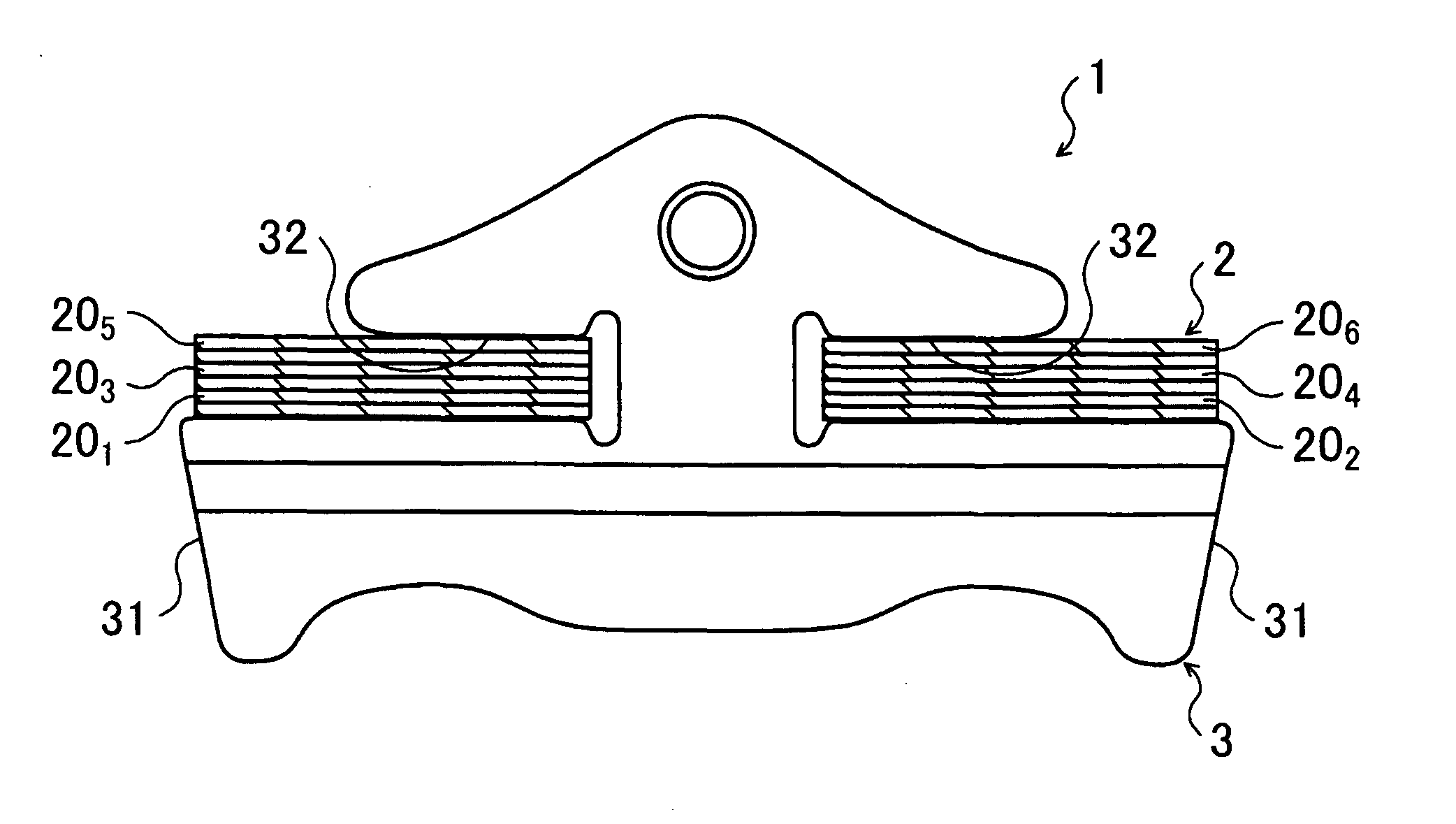
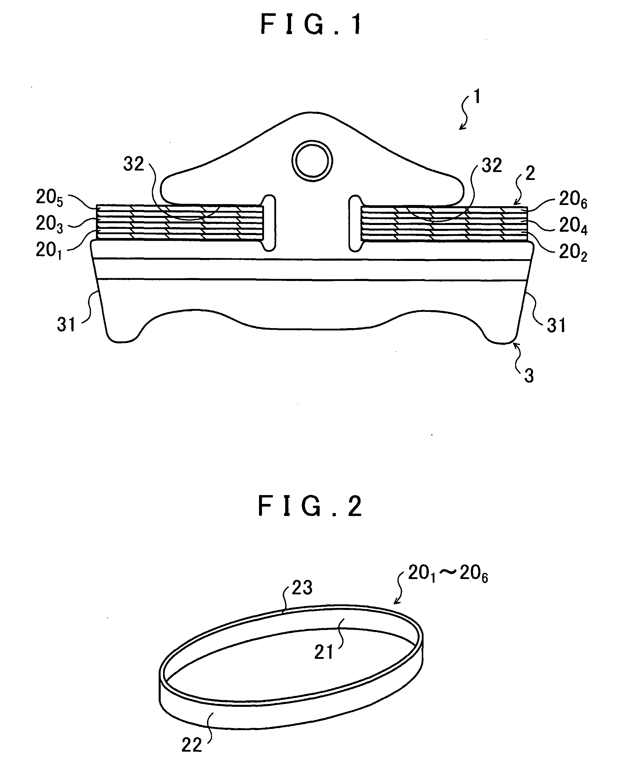
[0026]FIG. 1 is a partial cross-sectional view showing an example of a transmission belt 1 of the present invention. The transmission belt 1 shown in the drawing forms a continuously variable transmission (CVT), together with a primary pulley provided on a primary shaft as a drive-side rotating shaft, and a secondary pulley provided on a secondary shaft as a driven-side rotating shaft placed parallel to the primary shaft and a secondary pulley (none of these elements are shown). The transmission belt 1 is wrapped around a groove (a V-groove) of the primary pulley formed by a movable sheave and a fixed sheave, and a groove (a V-groove) of the secondary pulley similarly formed by a movable sheave and a fixed sheave, and transmits power applied to the primary shaft to the secondary shaft. At this time, by changing the groove width of at least one of the primary pulley and th...


PUM

PropertyMeasurementUnit
thicknessaaaaaaaaaa
thicknessaaaaaaaaaa
outer diameteraaaaaaaaaa

Abstract

A stacked ring 2 that forms a transmission belt is formed by stacking a plurality of elastically deformable ring materials 201 to 206 together. Shot peening is performed on surfaces of the ring materials 201 to 203 of the first layer as the innermost layer to the third layer so that a residual compressive stress in the ring materials 201 to 203 is higher than that in the ring materials 204 to 206 of the fourth to sixth layers. The outer circumferential length of the ring material 203 of the third layer is longer than the inner circumferential length of the ring material 204 of the fourth layer, and the ring material 203 of the third layer is press-fit into the ring material 204 of the fourth layer.

Description

INCORPORATION BY REFERENCE[0001]The disclosure of Japanese Patent Application No. 2010-015781 filed on Jan. 27, 2010 including the specification, drawings and abstract and the disclosure of PCT Patent Application No. PCT / JP2010 / 073823 filed on Dec. 29, 2010 including the specification, drawings and abstract are incorporated herein by reference in its entirety.BACKGROUND OF THE INVENTION[0002]The present invention relates to a transmission belt and a manufacturing method thereof, and more particularly to a transmission belt that is applied to a belt-type continuously variable transmission, and a manufacturing method thereof.DESCRIPTION OF THE RELATED ART[0003]In related art, continuously variable transmissions are known which have a cage pulley that is structured by arranging a plurality of belt drive elements on a circumference having its center on a central axis or an assumed central axis so that the belt drive elements extend substantially parallel to the central axis or the assum...

Claims


Application Information

Patent Timeline
Patent Type & Authority Patents(United States)
IPC IPC(8): F16G1/26B32B37/14
CPCB21D53/14F16G5/16Y10T29/49945Y10T156/10
Inventor OCHI, AKIRAMURATA, YOUICHIFUJII, KATSUMORIHATTORI, MASASHI
Owner AISIN AW CO LTD
Why Eureka
Try Eureka