Lateral flow assay test strip and method of making the same

a technology of lateral flow and test strips, which is applied in the field of lateral flow assay test strips, can solve the problems of inability to adapt to work as an absorbent, difficulty in manufacturing strips, and mechanical weakness of nitrocellulose, so as to increase the absorption capacity of the pad, and increase the absorption capacity

Active Publication Date: 2013-11-12
TEKNOLOGIAN TUTKIMUSKESKUS VTT
View PDF13 Cites 5 Cited by
  • Summary
  • Abstract
  • Description
  • Claims
  • Application Information

AI Technical Summary

Benefits of technology

[0008]Features and advantages of the use of bioactivable paper for the reaction membrane and the absorption pad are superior mechanical strength as compared to nitrocellulose and flexibility allowing the embossing and folding operations as well as modification of absorbency. Paper has a low price and when disposed, as opposed to nitrocellulose, it is biodegradable.
[0009]In an embodiment of the invention, the reaction membrane and absorption pad comprise an integral paper strip. The advantage is that there is no overlapping and joining of said two parts in the manner described e.g. in WO 2008 / 018073. The risk of inaccurate or variable overlap and non-uniformity of the strips as produced, which are major handicaps of the prior art, are wholly avoided, and the manufacture is considerably simplified.
[0011]In embodiments, the embossing made to the paper strip material may be protrusions forming a regular pattern over the absorption pad. Embossing is preferably combined with folding of the paper strip, the protrusions creating voids, i.e. empty air space between adjacent paper layers, which increase the absorption capacity of the pad. In this case the protrusions may be arranged between the folding lines, and both sides of the paper strip can be embossed so as to have protrusions between each pair of paper layers in the to-and-from configuration.

Problems solved by technology

However, a problem with nitrocellulose is its mechanical weakness.
The use of two materials as well as the two-part structure with a glue joint between the parts thus complicate the manufacture of the strip.
As regards nitrocellulose the material is too brittle for that and could not be adapted to work as an absorbent.
A commercial test strip, in which the membrane and the absorption pad are both of glass fibre, is available, but the lateral flow speed in such a strip is too high and causes a sensitivity problem.

Method used


Image

  • Lateral flow assay test strip and method of making the same
  • Lateral flow assay test strip and method of making the same
  • Lateral flow assay test strip and method of making the same

Examples


Embodiment Construction

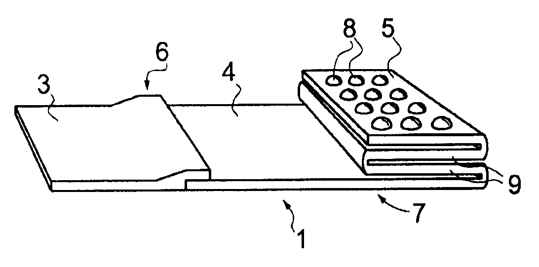
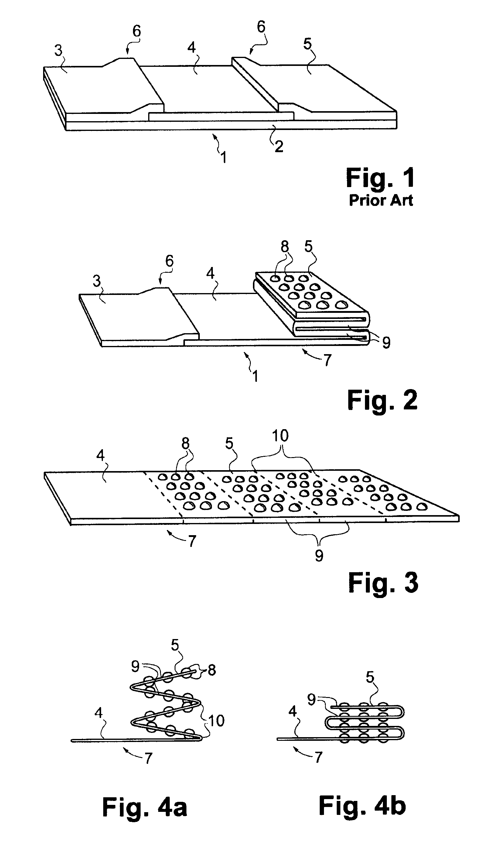
[0025]The prior art lateral flow assay test strip 1 of FIG. 1 comprises a non-absorbing backing laminate 2 supporting a sample pad 3, a reaction membrane 4 and an absorption pad 5. The sample pad 3, the reaction membrane 4, and the absorption pad 5 are separate parts, joined by controlled overlaps 6 and gluings between the sample pad 3 and the reaction membrane 4, and between the reaction membrane 4 and the absorption pad 5, respectively. A non-absorbing top laminate (not shown) may be placed to partially cover said three successive parts 3, 4 and 5 of the strip 1. The sample pad 3 can be made of glass fiber or filter paper, the reaction membrane 4 is made of nitrocellulose, and the absorption pad 5 is made of cellulose or filter paper.

[0026]The test strip 1 shown in FIG. 1 is used by bringing a liquid sample to be tested onto the free upper surface of the sample pad 3, uncovered by a top laminate (if any). The liquid is drawn to the reaction membrane 4 activated by provision of at ...


PUM

PropertyMeasurementUnit
capillary forceaaaaaaaaaa
mechanical weaknessaaaaaaaaaa
sizesaaaaaaaaaa

Abstract

The invention relates to a lateral flow assay test strip and a method for making the same. The strip comprises, in the flow direction, a selectively activated membrane for a test reaction and an absorption pad, which are both made of paper and may comprise an integral paper strip. The absorption pad has the paper strip embossed and / or folded to increase the strip's absorption capacity. The folded pad may have an accordion-like configuration, the strip running to-and-from, or it may have the strip rolled and then flattened to a stack of layers.

Description

PRIORITY CLAIM[0001]The present application is a National Phase entry of PCT Application No. PCT / FI2010 / 050358, filed May 3, 2010, which claims priority from Finnish Application Number 20095503, filed May 4, 2009, the disclosures of which are hereby incorporated by reference herein in their entirety.FIELD OF THE INVENTION[0002]The invention concerns a lateral flow assay test strip comprising, in the flow direction, a selectively activated membrane for a test reaction and an absorption pad, as well as a method of making such a test strip.BACKGROUND OF THE INVENTION[0003]Assay tests are used in vitro medical diagnostics to detect biomolecules such as enzymes or antibodies in liquid samples derived from patients. Testing means, usually in the form of a test strip, comprise a reagent chosen to be selectively reactive with the biomolecule to be detected or a derivate thereof, yielding a reaction product, the presence of which can be seen visually or shown by detection means.[0004]A typic...

Claims


Application Information

Patent Timeline
Patent Type & Authority Patents(United States)
IPC IPC(8): G01N33/48
CPCG01N33/558G01N33/521G01N33/54313G01N33/5436G01N33/54386D21H27/02A61L15/16D21H27/002G01N33/54388
Inventor LAPPALAINEN, TIMO
Owner TEKNOLOGIAN TUTKIMUSKESKUS VTT
Why Eureka
Try Eureka